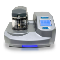
Q150T Sample Preparation System
Q150T - Instruction Manual 5 10473 - Issue 5
List of Figures
Figure 1-1. Front view of the Q150T................................................................................................8
Figure 2-1. Q150T Rear Panel ......................................................................................................12
Figure 2-2. Gas connectors with filter (part no. 12842) fitted to purge gas inlet ............................13
Figure 2-3. Power outlet lead wiring...............................................................................................14
Figure 2-4. Fitting the standard stage............................................................................................16
Figure 3-1. Standby screen ...........................................................................................................17
Figure 3-2. Selecting a profile........................................................................................................18
Figure 3-3. A run in progress: with FTM installed (left) and without FTM (right). ..........................19
Figure 3-4. Venting the chamber: with FTM installed (left) and without FTM (right)......................19
Figure 3-5. Listing system properties for a profile..........................................................................20
Figure 3-6. Changing the Stage Rotate system property...............................................................20
Figure 4-1. Profile Editor................................................................................................................21
Figure 4-2. Creating a new profile..................................................................................................23
Figure 4-3. Entering a new profile name........................................................................................23
Figure 4-4. Editing Profile Parameters...........................................................................................24
Figure 4-5. Materials Editor ...........................................................................................................25
Figure 4-6. Material Parameters ....................................................................................................27
Figure 5-1. QT Metal evaporation process ....................................................................................31
Figure 5-2. Typical 12nm Controlled pulse evaporation .................................................................33
Figure 5-3. Wedge tool (Part No. 12097) ......................................................................................35
Figure 5-4. (l) A finished wedge-shaped rod; and (r) in position with plain rod ..............................35
Figure 5-5. Ramped Profile with default parameters......................................................................36
Figure 5-6. Prompts to repeat the outgas procedure (left) and proceed with coating (right) ..........39
Figure 5-7. Aperture cleaning in progress .....................................................................................41
Figure 6-1. System Editor..............................................................................................................43
Figure 6-2. Network properties ...................................................................................................... 44
Figure 6-3. Active ftp address .......................................................................................................44
Figure 6-4. Generic sputter parameters.........................................................................................45
Figure 6-5. Vacuum parameters ....................................................................................................46
Figure 6-6. Maintenance settings ..................................................................................................47
Figure 6-7. Hardware settings (single target) ................................................................................48
Figure 6-8. Changing the user level...............................................................................................49
Figure 6-9. Managing user groups ................................................................................................50
Figure 6-10. FTM Status .................................................................................................................51
Figure 6-11. Setting the date and time.............................................................................................51
Figure 6-12. Connecting the Q150 to a network ..............................................................................52
Figure 6-13. Process log and browse buttons .................................................................................53
Figure 6-14. Process log detail ........................................................................................................53
Figure 7-1. Top view of the sputter insert ......................................................................................54
Figure 7-2. Sputter insert and target assembly.............................................................................. 55
Figure 7-3. Carbon Rod Insert.......................................................................................................56
Figure 7-4. Recommended Carbon Rod shapes ........................................................................... 57
Figure 7-5. Carbon Rod Shaper (S8650/S8651))..........................................................................57
Figure 7-6. Carbon string insert.....................................................................................................58
Figure 7-7. Fitting the metal evaporation insert for downwards evaporation...................................59
Figure 7-8. Metal evaporation insert adapted for upwards evaporation ..........................................61
Figure 7-9. Glow discharge insert..................................................................................................62
Figure 7-10. Removing the shutter ..................................................................................................63
Figure 7-11. Rotacota stage ............................................................................................................ 64
Figure 7-12. Slide stage ..................................................................................................................65
Figure 7-13. Large (102mm) Sample Stage and gearbox................................................................66
Figure 7-14. Adjustable tilting stage ................................................................................................67
Figure 7-15. FTM (left); replacing the FTM crystal (centre); FTM lead (right) .................................68
Figure 7-16. The extended height cylinder in position......................................................................69
Figure 7-17. Rotating vacuum spigot...............................................................................................70
Figure 7-18. The emergency stop module .......................................................................................71
Figure 7-19. Connecting the emergency stop module .....................................................................71
Figure 9-1. Sputtering Deposition Rate using Gold .......................................................................85
Figure 9-2. Sputtering Deposition Rate using Chromium ..............................................................86
Figure 9-3. Sputtering Deposition Rate using Silver ......................................................................87

 Loading...