Instruction Reference Manual 127
Description
Rotates to the right the data whose address is:
• the data in HL, or
• the sum of the data in IX and a displacement d,or
• the sum of the data in IY and a displacement d.
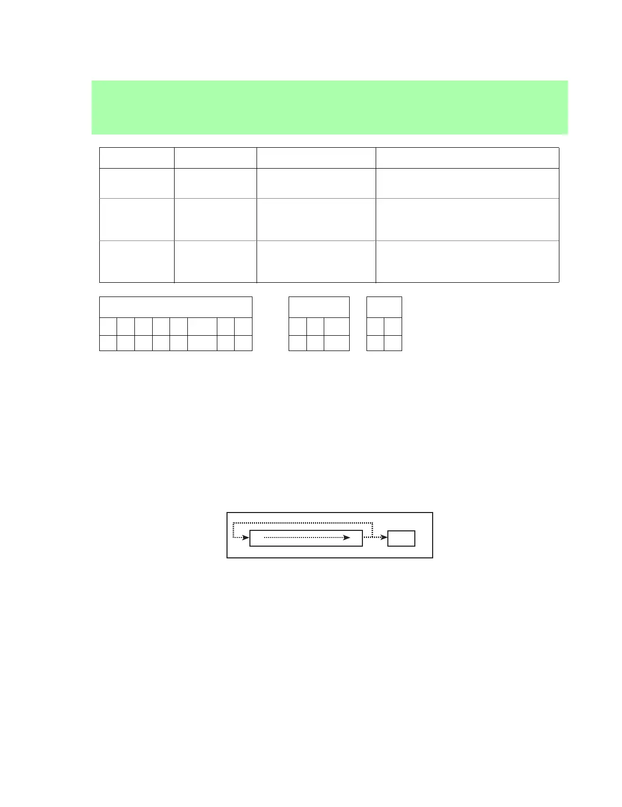
Each bit in the register moves to the next lowest-order bit position (bit 7 moves to bit 6, etc.) while bit 0
moves to both bit 7 and the C flag. See figure below.
Figure 6: The bit logic of the RRC instruction.
RRC (HL)
RRC (IX+d)
RRC (IY+d)
Opcode Instruction Clocks Operation
CB 0E RRC (HL) 10 (2,2,1,2,3) (HL) = {(HL)[0],(HL)[7,1]};
CF = (HL)[0]
DD CB d 0E RRC (IX+d) 13 (2,2,2,2,2,3) (IX + d) = {(IX + d)[0],
(IX + d)[7,1]};
CF = (IX + d)[0]
FD CB d 0E RRC (IY+d) 13 (2,2,2,2,2,3) (IY + d) = {(IY + d)[0],
(IY + d)[7,1]};
CF = (IY + d)[0]
Flags ALTD I/O
S Z L/V C F R SP S D
• • L • • • •
7
0
CF