Chapter 2
Radar positioning and installation
2.1 Positioning
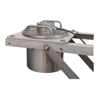
Figure 2.1: The 5
◦
[deg] half
top angle of the F08 antenna
beam and the reference level
for mounting height measure-
ment.
For obtaining the best results from a WaveGuide Onboard the
following radar positioning criteria must be taken into account:
• It is advised to choose a mounting position such that the
WaveGuide radar beam is free of large reflecting obstacles
(the beam of the F08 antenna has a 5
◦
[deg] half top angle
as shown in Fig. 2.1). The minimum horizontal distance
between the radar and any obstacle in the beam’s path
should be at least 10% of the vertical distance between
the radar and the obstacle. This does not only include
horizontal objects in the beam’s path but also vertical
structures.
• Any structure that the WaveGuide radar is mounted to
might have some influence on the wave flow around it.
Hence, it is advised to mount the radar at a position facing
the mean wave direction so that the radar can measure
the least disturbed water surface. In most cases the ship’s
bow provides the optimal mounting position but as each
vessel has a unique shape, it is the user’s responsibility
to carefully identify the best position for mounting the
WaveGuide radar.
• The reference level for the mounting height of the radar
is shown in Fig. 2.1.
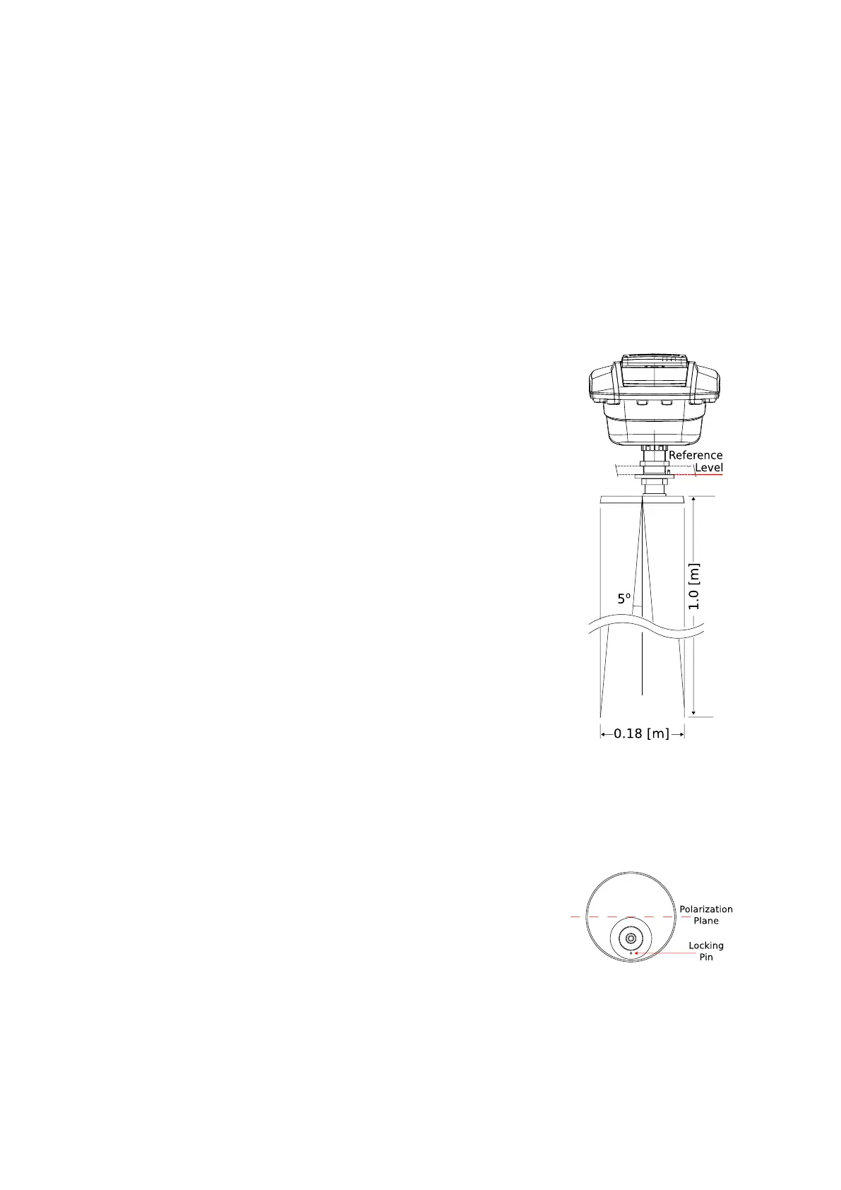
• Figure 2.2, shows the polarization plane of the signal emit-
ted from the radar antenna. If the WaveGuide radar is
mounted close to a large vertical wall, then the radar
should be mounted such that the polarization plane is
parallel to the wall. That is to minimize the effect of the
wall on the propagation of the signal. Nevertheless, the
horizontal distance between the radar and the wall should
comply with the previous criteria.
• A vertically mounted radar (0
◦
[deg] tilt angle) results
in optimal performance. But if necessary the WaveGuide
radar can be mounted with a maximum tilt angle of 15
◦
[deg] (tilted to face the direction away from the structure
it is mounted on).
Figure 2.2: Top view of radar
antenna and its polarization
plane.
9