2.5 Housing
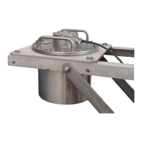
Figure 2.8: Cover A.
Figure 2.9: Cover B.
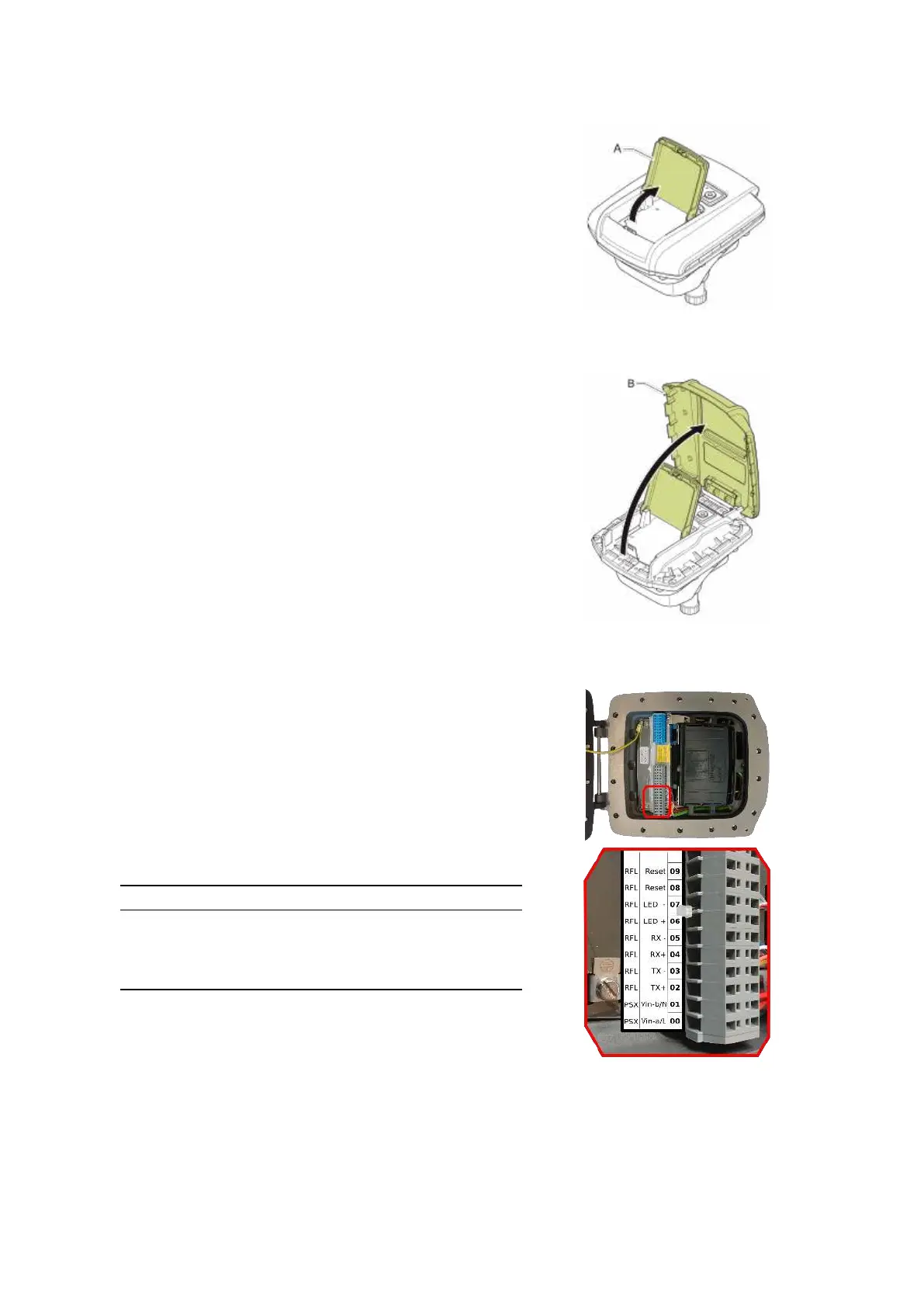
Figure 2.10: Terminal compart-
ment and connections.
To access the WaveGuide radar case:
• Open cover A as shown in Fig.2.8.
• Open and remove cover B as shown in Fig.2.9.
• Use an 8 [mm] Allen key to loosen the 16 bolts of the
housing. Make sure the 4 bolts on the side of the hinge
are entirely screwed into the cover and do not protrude
beyond the flange of the housing. Otherwise the flange
of the housing can be damaged when closing the cover.
• Open the housing cover.
2.6 Wiring
The housing contains two sets of connector blocks as well as
multiple ground connection points.
Figure 2.10 shows the connector blocks and the sequence of
relevant poles. The poles number 00 labeled PSX:Vin-a/L
and 01 labeled PSX:Vin-b/N are used to supply the system
with either 24-65 [VDC] or 65-240 [VAC] power. The internal
power supply is reverse polarity protected hence the polarity
of the connected wires does not matter.
Please do take into account the voltage drop due to wire resis-
tance between the power supply unit and the radar, the radar
must at all times receive more than 21.0 [VDC]. For this rea-
son, to be sure to stay within the limits, at longer distances
it is advised to use a 36 [VDC] or a 48 [VDC] power supply.
The poles numbered 02, 03, 04 and 05 labeled RFL:Tx+,
RFL:Tx-, RFL:Rx+ and RFL:Rx- relate to Ethernet data
RJ45 pins 1, 2, 3 and 6.
Label RJ45 Profinet Color
Tx+ 1 Yellow
Tx- 2 Orange
Rx+ 3 White
Rx- 6 Blue
Table 2.1: Ethernet wiring instruction.
12