2.3 Cable
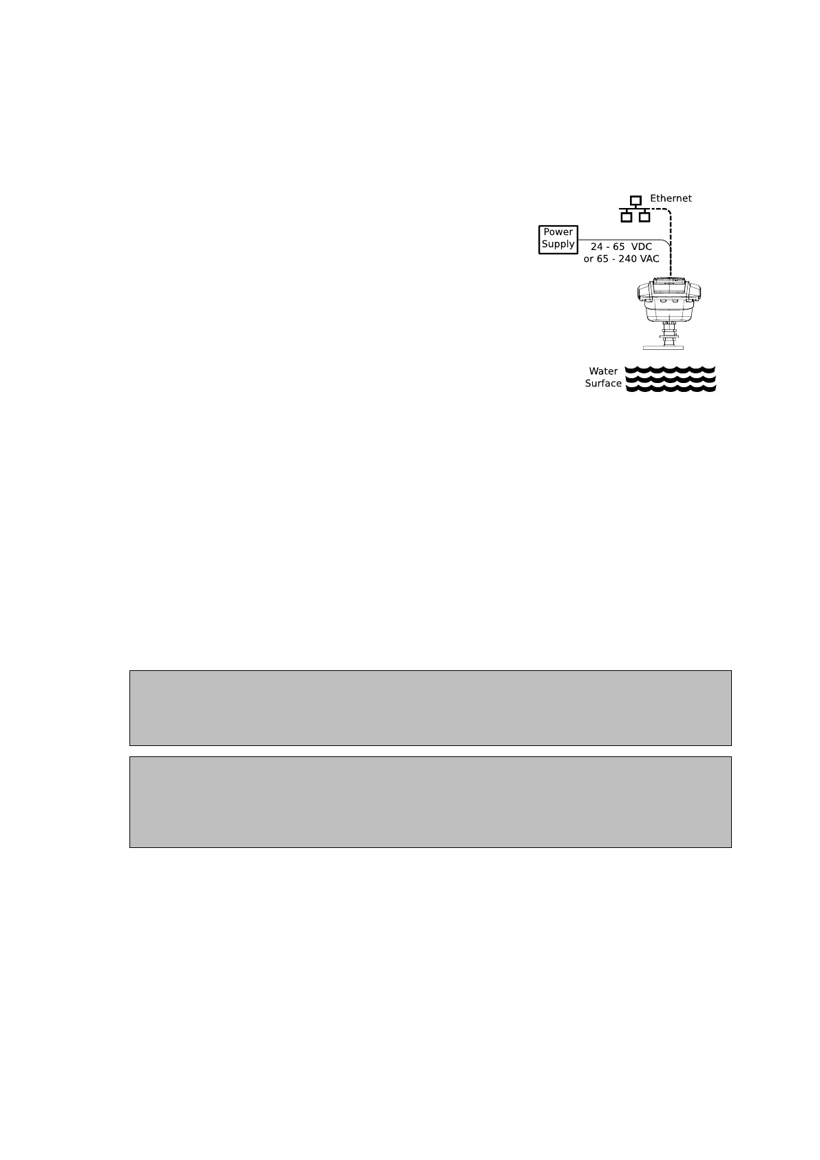
Figure 2.7: Block diagram of the
Waveguide Onboard system.
When selecting a cable for use with a WaveGuide system,
the following requirements must be used:
• Two wires for power transmission. The choice of power
supply will influence the diameter and insulation thick-
ness of those wires.
• Four wires for data transmission. The use of an
Ethernet data connection necessitates the use of four
twisted-pair wires (22-24 [AWG] and minimum insu-
lation thickness of 0.245 [mm]).
• The cable must be shielded and can have a maximum
length of 80 [m].
Upon request, Radac can supply an optional cable that com-
plies with the WaveGuide system requirements for power
and data transmission.
2.4 Gland
Depending on local regulations, this device can be connected by using glands, direct entry,
or conduits
An explosion proof (Ex-d) compound cable gland (M20), plus a M20 to 3/4" NPT converter
are supplied with each WaveGuide radar for use as a safe and watertight cable entry point.
The supplied gland allows the installation of cables from 6.5 to 11.9 [mm] in diameter.
Two approved 3/4" stopping plugs are provided for sealing the unused cable inlets
Note
Instructions supplied by the manufacturer for installing the included cable gland are
provided separately in its packaging.
Caution
The use of Ex-d certified materials of an inappropriate IP value or the improper
installation of cable glands, conduits or stopping plugs will invalidate the Ex approval of
the WaveGuide.
11