2.2 Installation
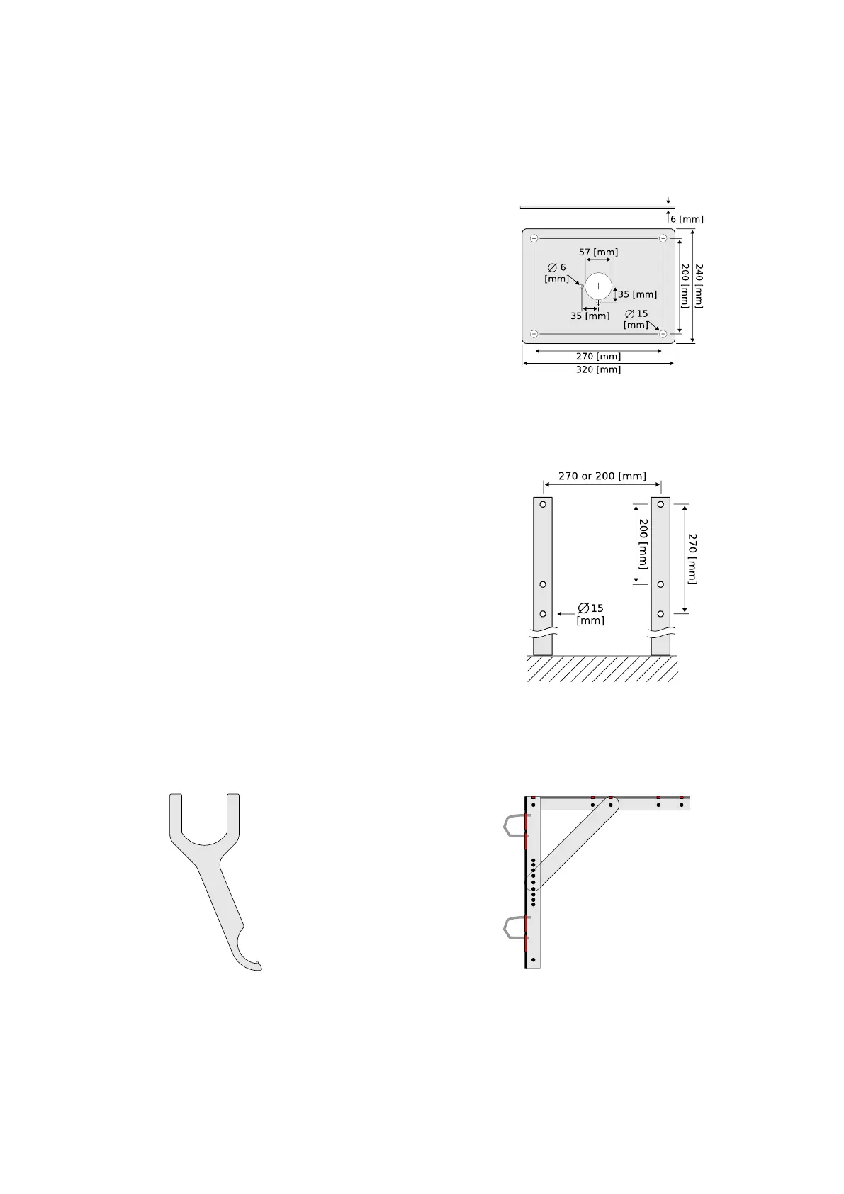
Figure 2.3: Optional mounting
plate for the WaveGuide radar
(Part no. WG-MP-EX).
To facilitate the mounting of the WaveGuide radar, an op-
tional mounting plate is available upon request (Part no.
WG-MP-EX). Figure 2.3 shows a sketch of the optional
mounting plate and its dimensions.
The mounting plate can be fixed to two horizontal beams
(Fig. 2.4). The length of the beams must take into account
the minimum horizontal distance between the WaveGuide
radar and any obstacles in the path of the radar signal (as
explained in the radar positioning criteria). Each beam must
have 2 holes either 200 or 270 [mm] apart dep ending on the
intended orientation of the mounting plate.
It is advised to mount the horizontal beams first. Then to
attach the mounting plate to the horizontal beams and fi-
nally to mount the WaveGuide radar to the mounting plate.
Mounting the radar is done by mounting the radar antenna
to the mounting plate and then mounting the radar housing
to the antenna.
Figure 2.4: Top view of the hori-
zontal mounting beams.
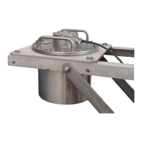
Radac can provide an optional dual-purpose wrench/spanner
(Part no. WG-EX-tool). One end of the wrench (Fig. 2.5)
is an open-end wrench that can be used to tighten the an-
tenna to the mounting plate. While the other end is a pin
wrench that can be used for tightening the radar housing to
the antenna. Upon request, Radac can supply an optional
frame (Part no. WG-MH-EX) that allows for mounting the
WaveGuide radar and mounting plate at angles 0, 5, 10,
15 and 20 [deg] away from vertical (see Fig.2.6). The radar
mounting plate (Part no. WG-MP-EX) is included with this
frame as well as brackets to allow mounting the frame to a
handrail.
Figure 2.5: Optional wrench
that allows mounting of the
WaveGuide radar (Part no.
WG-EX-tool).
Figure 2.6: Optional frame that
allows mounting of the Wave-
Guide radar at different angles
(Part no. WG-MH-EX).
10