Radio Systems Millenium-D Digital Console Page 10
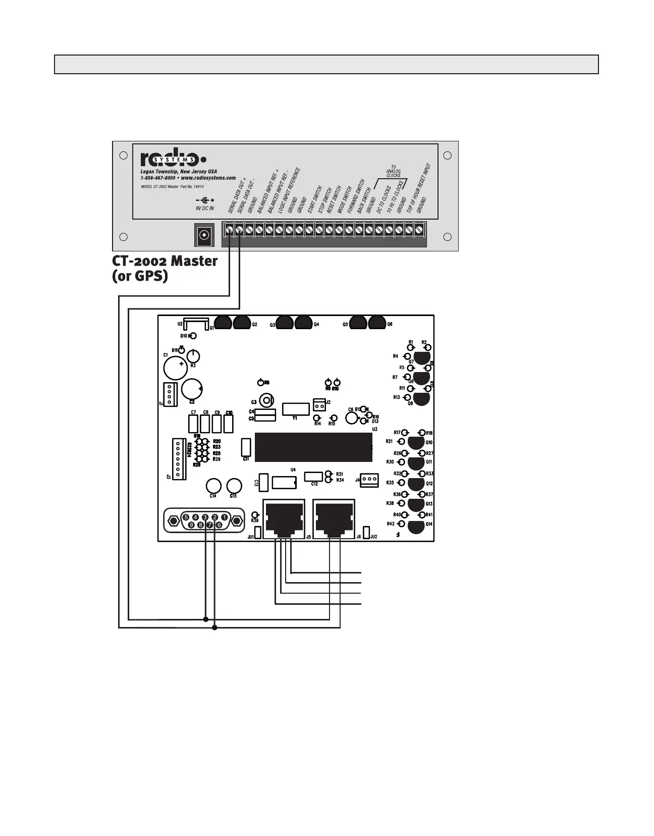
Pin 6
Serial
Data In -
Pin 3
Serial
Data In +
Pin 1 Serial Data Out +
Pin 2 Serial Data Out -
Pin 3 Serial Loop Out +
Pin 6 Serial Loop Out -
Out to additional clocks
(up to 32)
J7 (9 Pin D Female)
Pin 1 Serial Data Out +
Pin 2 Serial Data In +
Pin 3 Serial Data In -
Pin 4 Serial Data Out -
Pin 5 GND
Pin 6 TOH Reset
Pin 7 GND
Pin 8 N/C
Pin 9 N/C
J5 Serial Loop-Thru Output (RJ-45)
Pin 1 Output +
Pin 2 Output -
Pin 3 Input +
Pin 4 GND
Pin 5 TOH Input
Pin 6 Input -
J6 Serial Input (RJ-45)
Pin 1 n/c
Pin 2 n/c
Pin 3 Input +
Pin 4 GND
Pin 5 TOH Input
Pin 6 Input -
Note: Use pins 1&2 if this clock is the master
(first) in the serial chain (a crossover cable is
recommended). Use pins 3&6 iflooping thru
sync provided externally via J6 (a straight-thru
cable is recommended)
J7
J5
J6
+
-
-
+
* S/N RS-14503 11/2003) and later
Illustration A-2
CT-2002 Console Clock/Timer Wiring Diagram