Radio Systems Millenium-D Digital Console Page 41
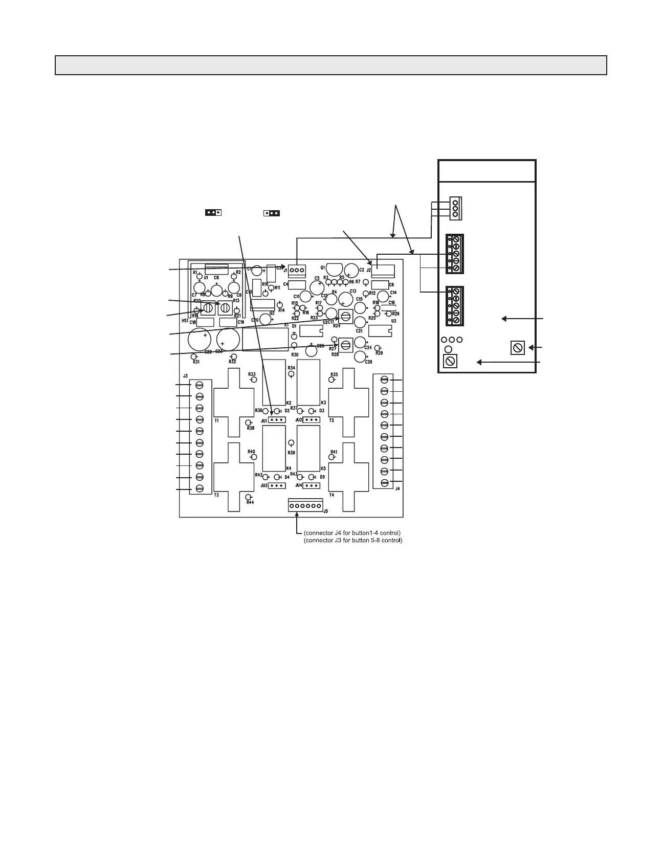
Illustration E-5
Intercom Wiring Card
To Interconnect the Intercom Card to Radio Systems’ Millenium Analog Consoles
Wiring
1. Connect utility output (typically with operators mic prefader/pre on-off assigned) (or other line level source) to output
board talk-back input (J37 pins 1 & 2).
2. Connect provided patch cables from intercom card to output board (control cable from intercom card J1 to console
connector J1 and the audio cable from intercom card J2 to console conenctors J36 & J37).
3. Connect up to four table-top speakers to terminals labeled “table-top speaker hot” and “table-top speaker switched”
(1-4). Use shielded cable. Consult interconnection diagram on next page for hook-up. Select table-top speaker on con-
sole selector buttons for hands-free mode. Table-top speakers can “call” the console via call button.
4. Connect up to four console intercoms to terminals labeled “console intercom +” and “console intercom -”.
Consoles must select each other to establish a push-to-talk pathway.
5. Maximum of four stations “any combination of table-top and console” may be connected.
6. Set VR2 for Intercom output level and set VR26 for Intercom input level
Installation
When ordered with the console, this optional board normally will be factory-installed.
For field installation, use the four plastic stand-offs provided to mount the board on the inside rear console wall near the
associated input and output and wire it to the output board with the two (supplied) harness cables.
5 (Cue In)
4
3
2
1
Intercom Control
(To J1 on the Output Bd.)
Table Top Speaker
Drive Volume
Remote Console
Drive Volume
Table Top Speaker
Receive Volume
Remote Console
Receive Volume
Console Intercom 1 +
Console Intercom 1 -
Shield
Table Top Speaker 1 Hot
Table Top Speaker 1 Switched
Console Intercom 2 +
Console Intercom 2 -
Shield
Table Top Speaker 2 Hot
Table Top Speaker 2 Switched
Table Top Speaker 4 Switched
Table Top Speaker 4 Hot
Shield
Console Intercom 4 -
Console Intercom 4 +
Table Top Speaker 3 Switched
Table Top Speaker 3 Hot
Shield
Console Intercom 3 -
Console Intercom 3 +
From designated utility output
5
4
3 GND
2
1 TB Out
Output Board
Talk-Back Connectors
3 +15V
2 GND
1 Squawk Ctl
These pre-made factory
cables included with
the squawk box card
Intercom Input Level Set
To Digital Output Board
Intercom Output Level Set
( External Cue Input - located
on circuit board far right)
J1
J36
J37
Table-top/Console Programming
(Program J1 thru J4)
Jump left pins
for table-top
Jump right pins
for console
1
2
3
4
5
6
7
8
9
10
10
9
8
7
6
5
4
3
2
1
VR2
VR26
Intercom udio
(To J36 J3 on
the output bd.)
Int. In -
Int. In +
J2-2
J2-3
J2-1