Home
Radio Systems
DJ Equipment
Millenium-D
Radio Systems Millenium-D User Manual
4
of 1
of 1 rating
94 pages
Give review
Manual
Specs
To Next Page
To Next Page
To Previous Page
To Previous Page
Loading...
Radio Systems Millenium-D Digital Console
Page 93
Help Screens
This pull-down men
u contains help
and informational screens including:
1 - “Help About” software v
er
sion informa-
tion
2 - Help messages
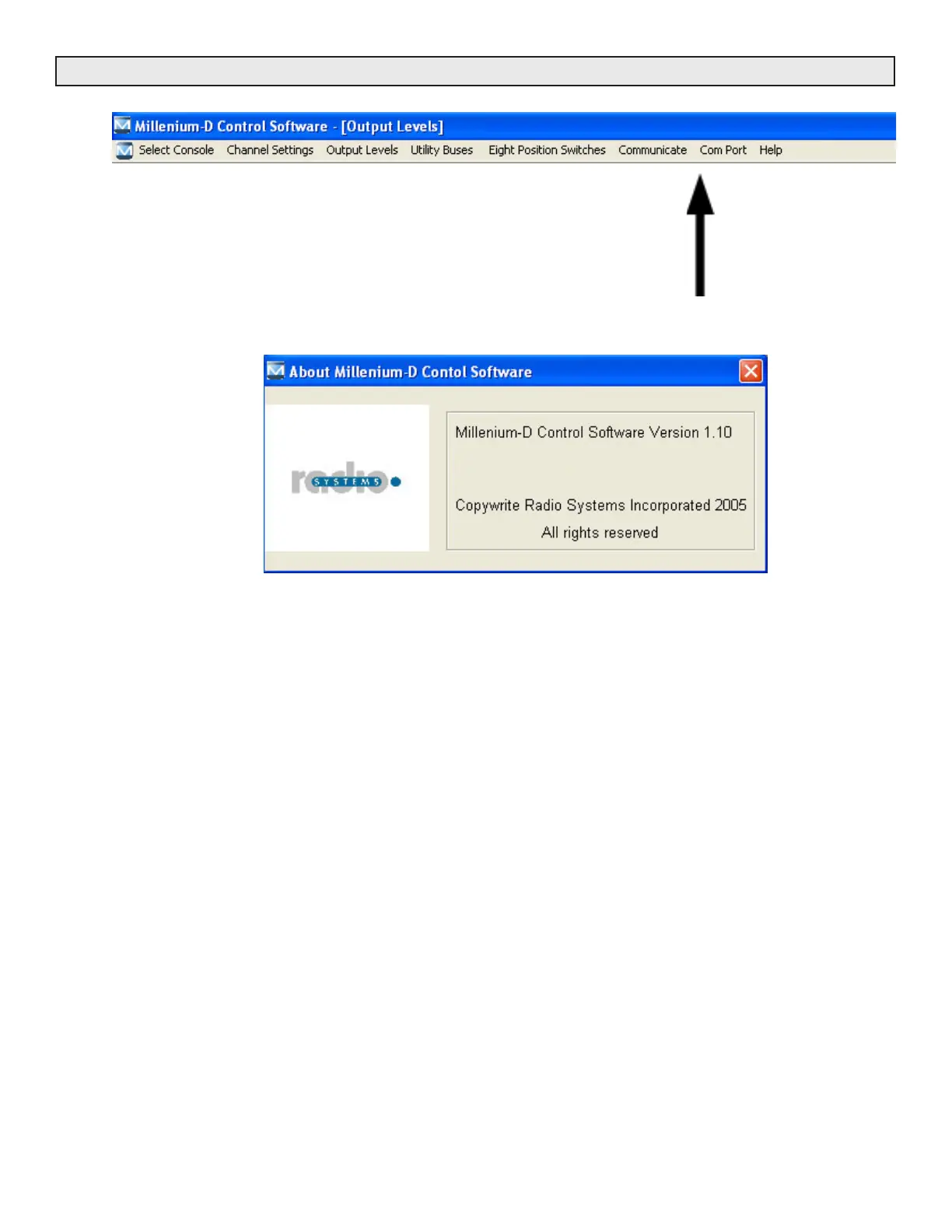
Screen #1
About Millenium D
Select to view software version information.
A
utomatically upda
ted w
hen new software revisions are installed.
92
94
Table of Contents
Default Chapter
2
Table of Contents
2
Installation/Wiring/Operation
5
Console Placement
5
Opening the Console
5
Power Supply
5
Installation
5
Wiring Access Layout
5
Audio Inputs
5
Audio Outputs
5
Control
6
Audio Connectors
6
Wiring Quick Connectors
6
Grounding and Shielding
6
Operation
6
Input Assignment
6
MIC Use
7
Cue Circuitry
7
Output Routing
7
Utility Buses
7
MIX-Minus Via the PROGRAM.3 (Formerly the "TEL") Bus
7
Monitor Amplifier Output Select
7
Headphone Amplifier Output Select
8
Remote Control
8
Eight Position Switcher
8
Console Clock Timer
8
Illustration
9
CT-2002 Console Clock/Timer/Master Clock
9
Illustration
10
CT-2002 Console Clock/Timer Wiring Diagram
10
Illustration
11
LED Meter Board with Talkback Microphone
11
Six Channel Control Board
12
Overview
12
Function Programming
12
Channel Power-Up Mode
12
Remote Control Options - by Channel
12
Remote Control Options - by Input
13
2.2.3.1 Pulse/Holding Remote Control
13
2.2.3.2 Send Through Of Remote On/Off Commands
13
Muting Buses
13
Timer Reset
13
Cue Options by Channel
14
2.2.6.1 Cue On Fader Detent
14
2.2.6.2 Auto Cue
14
2.2.6.3 Cue Defeat On Channel On
14
2.2.6.4 Cue Exclusive
14
Cue Options by Input
14
Off (Ready) Lamp Options
14
Analog/Digital Programming
15
2.2.10 Remote Control Connector
15
2.2.11 Optional Remote Control Board
15
Monitor Control Board
15
Illustration
16
Six Channel Control Board Jumper Settings
16
Illustration
17
Remote Control Wiring (Factory Default with Cue for IFB)
17
Illustration
18
Remote Control Wiring ("Classic" Mode)
18
Six Channel Audio Mother Board
19
Input Connectors
19
Input Configurations
19
Input Wiring
19
Analog Daughter Cards
19
Unbalanced Analog Audio
19
Analog Mono Inputs - for MIC and Line Level
19
Input Sensitivity
19
Phantom Power
20
Digital Daughter Cards
20
Unbalanced Digital Audio
20
Patch-Point" Connections
20
Illustration
21
Analog Input Plug-In Board P/N 15303
21
Illustration
22
Digital Input Plug-In Board 15304
22
Illustration
23
Input Mother Boardrj-45 Connector Version
23
Illustration
24
Output Boards
25
Overview
25
Analog Output Board
25
PROGRAM.1 and PROGRAM.2 Analog Outputs
25
PROGRAM.3 (Formerly "TEL") Output
26
External Monitor and Headphone Inputs
26
Headphone Outputs
26
Monitor Sends
26
Digital Output Board
27
Digital Program Outputs
27
Digital Utility Outputs
27
RS-232 Connectivity
27
Clock Rate (Digital Sync.)
28
Eight Position Switcher
28
Control Wiring
28
Mute and Timer Reset Bus Connections
28
Talk Back Connections
28
Intercom Kit
29
Internal Adjustments and Level Calibration
29
Program Bus Output Level Adjust
29
VU Meter "0" Calibration
30
Peak LED Trip Point Calibration
30
External Monitor Input Level
30
Cue Bus External Input Level
30
Illustration
31
Analog Output and Meter Board 5-Pin
31
Illustration
32
Analog Output and Meter Board RJ-45
32
Illustration D-4 Digital Output and Processor Board 5-Pin
34
Illustration
35
Auxiliary Control Relay Wiring
35
Illustration
36
Talkback Wiring
36
Illustration
37
Enhanced Remote Interface Card
37
Illustration
38
Four Source Router Card
38
Illustration
39
DA Mixer Card
39
Illustration
40
DA Mixer Card Programming Examples
40
Illustration
41
Intercom Wiring Card
41
Intercom Card Table-Top Speaker & Console Interconnection
42
Description - Overview
43
Operation
43
Installation and Wiring
43
Control Wiring
43
Intercom Card Audio Wiring
43
Console Internal Wiring
43
Console Interconnection
44
Calibration
44
Using Active Balanced Circuitry
45
Six Channel Control Board Schematic F-1
46
Parts Layout F-2/3
47
Parts List F-4/5
48
Monitor Board Schematic F-6
49
Parts Layout F-7/8
52
Parts List F-9
54
CT-2002 Clock/Timer Schematic F-10/11
55
Parts Layout F-12
57
Parts List F-13/14/15
58
Analog Output Board Schematic F-16/17/18
61
Parts Layout F-19
64
Parts List F-20/21/22
65
Power Supply Interface Schematic F-23
68
Parts Layout F-24/25
69
Parts List F-26
71
Console da Mixer Schematic F-27/28
72
Parts Layout F-29
74
Parts List F-30
75
Console VU Meter Schematic F31
76
Console VU Meter Schematic F32
77
Millenium Digital Console Specifications
78
Frequency Response
79
Millenium Digital Consoles Parts Ordering
80
Millenium Consoles - Warranty and Repair Policies Warranty
81
Repair Policy
81
Return Instructions
81
Millenium - Digital Console Software
82
Overview
82
Utility Buses
82
Output Levels
82
Channel Settings
82
Communications/Serial COM Port
82
Position Switches
90
Help Screens
93
4
Based on 1 rating
Ask a question
Give review
Questions and Answers:
Need help?
Do you have a question about the Radio Systems Millenium-D and is the answer not in the manual?
Ask a question
Radio Systems Millenium-D Specifications
General
Brand
Radio Systems
Model
Millenium-D
Category
DJ Equipment
Language
English