Wiring Diagrams
Installation Guide CT100
Step-By-Step Wiring Diagrams
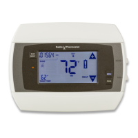
3 Wire Heat GAS MILLIVOLT or 24VAC
System
1. Connect the R (or RH) wire to the
RH terminal. This connects the
heat power.
2. Connect the W wire to the W
terminal. This connects the heat.
3. Connect the C wire to the C
terminal. Your HVAC system is now connected to the CT100.
4. Go to “Connect Your Wires” on page 9.
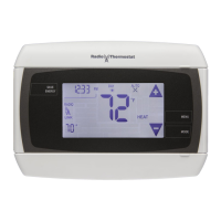
4 Wire Heat
1. Connect the R (or RH) wire to the
RH terminal. This connects the
heat power.
2. Connect the W wire to the W
terminal. This connects the heat.
3. Connect the G wire to the G
terminal. This connects the fan.
4. Connect the C wire to the C terminal. Your HVAC system is now
connected to the CT100.
5. Go to “Connect Your Wires” on page 9.
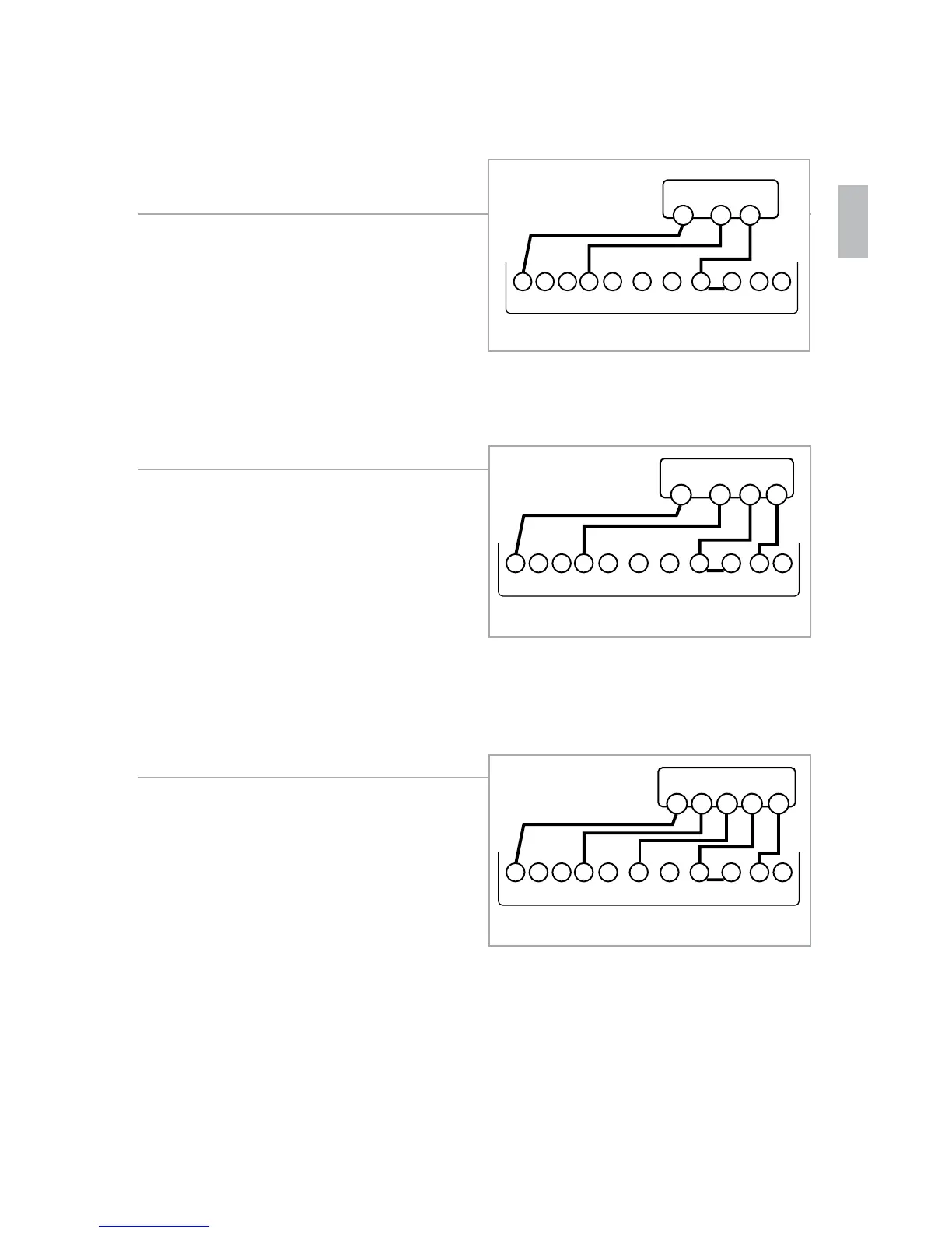
5 Wire Heat/Cool
1. Connect the W wire to the W
terminal. This connects the heat.
2. Connect the Y wire to the Y
terminal. This connects the
cooling compressor.
3. Connect the RH or R wire to the
RH terminal. This connects the
power.
4. Connect the G wire to the G terminal. This connects the fan.
5. Connect the C wire to the C terminal. Your HVAC system is now
connected to the CT100.
6. Go to “Connect Your Wires” on page 9.
POWER
HVAC SYSTEM
THERMOSTAT
CBOW YY2
RH
RC GAW2
W R
C
POWER
HVAC SYSTEM
THERMOSTAT
CBOW YY2
RH
RC GAW2
W R
C
G
POWER
HVAC SYSTEM
THERMOSTAT TERMINALS
CBOW YY2
RH
RC GAW2
W R
C
GY
19
 Loading...