ESP-2WIRE Controller
2
Installation
Replacing an Existing Controller
a
Take a photo of the wiring details, which will
be useful to reference when installing the new
controller.
b
Unplug power cord from the AC power outlet
and disconnect wires from controller.
Mount Controller
WARNING
Install the controller with the power
supply cord exit side pointing
downwards and through the leftmost
opening at the bottom of the controller.
a
Drive a mounting screw into the wall, leaving
an 1/8 inch gap between the screw head and
the wall surface (use the supplied wall anchors
if necessary).
b
Locate the keyhole slot on back of the
controller unit and hang it securely on the
mounting screw.
c
Open the front panel, and drive additional
screws through the open holes inside the
controller and into the wall.
b
c
Wall Mounting Method.
Outdoor Installation with Direct
Wiring
WARNING
• Electric shock can cause severe injury
or death. Make sure power supply is
turned OFF before connecting power
wires.
• Ground wire must be connected to
provide electrical surge protection.
• Permanently mounted conduit shall
be used for connecting main voltage
to the controller.
• When using fixed wiring to main
supply, the installation must
incorporate a disconnection device.
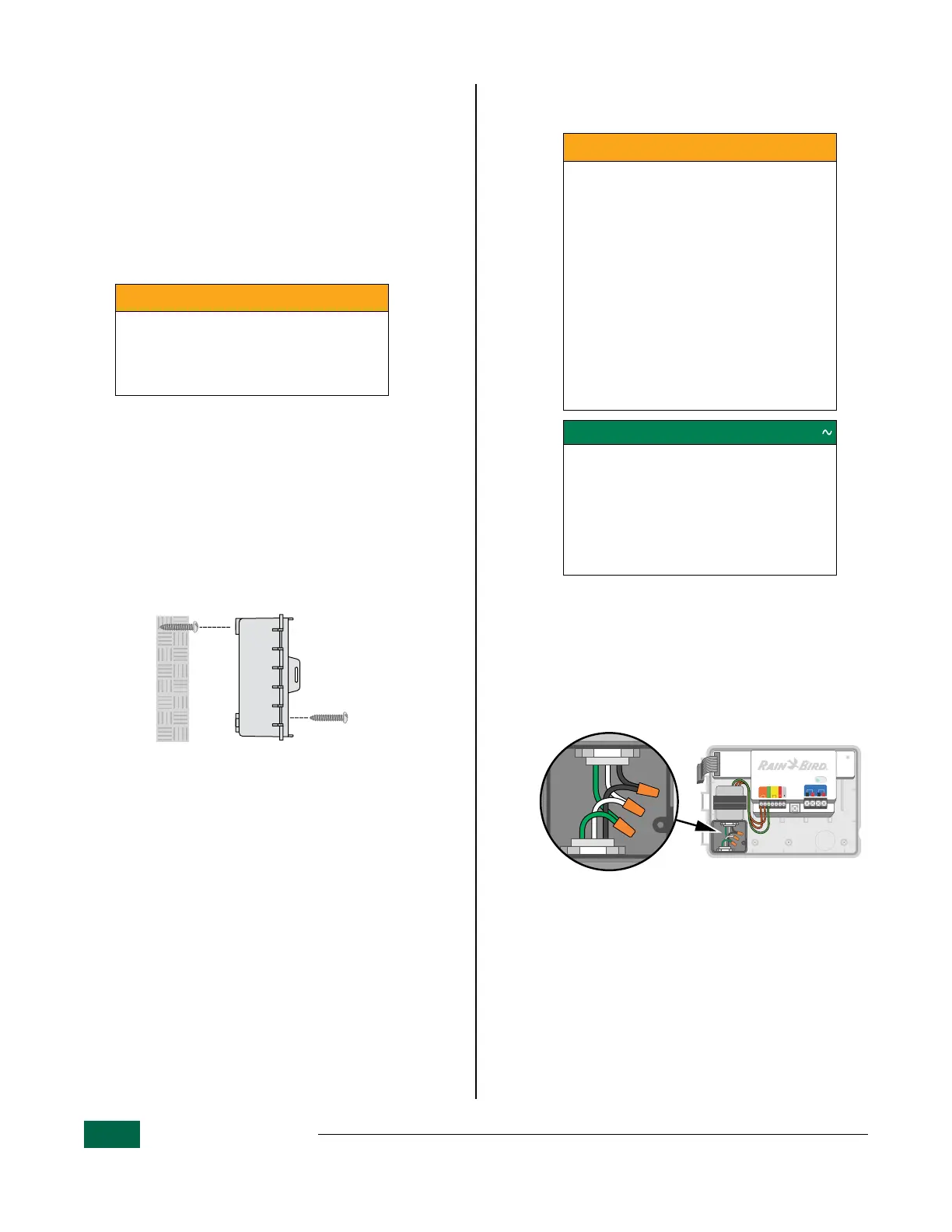
POWER WIRING CONNECTIONS 120 V
• Black supply wire (hot) to the black
transformer wire.
• White supply wire (neutral) to the
white transformer wire.
• Green supply wire (ground) to the
green transformer wire.
a
Route the three external power source wires
through the conduit opening at the bottom of
the unit and into the wiring compartment.
b
Using the provided wire nuts, connect the
external power source wires (two power and
one ground) to the transformer connection
wires inside the wiring compartment.
STATUS
FLOW
FLOW
GND
24VAC
ONLY
SENSOR
PATH 1PATH 2
AB AB
Direct Wiring Connection.