2
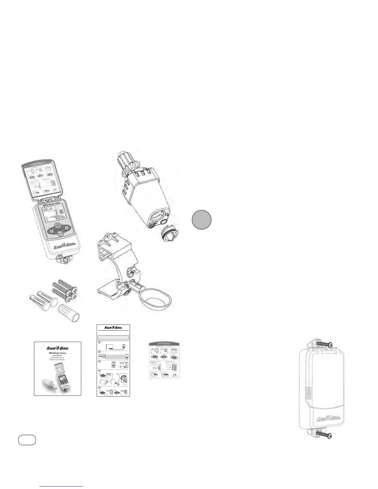
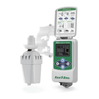
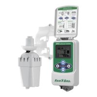
WR2 Wireless SensortXXXSBJOCJSEDPN83
WR2 Benets
t All settings are programmed through the Controller
Interface device
t Large easy to understand icons communicate irrigation
mode and sensor status.
t 4FOTPS-&%JOEJDBUPSFOBCMFTPOFQFSTPOTFUVQSFEVDJOH
installation time
t Battery is easy to install / replace
t "FTUIFUJDBQQFBSBODFOPFYUFSOBMBOUFOOBT
t &BTZUPJOTUBMMTFMGMFWFMMJOHTFOTPSCSBDLFUNPVOUTUPøBU
surfaces or rain gutters
t “Quick Shut O” interrupts active irrigation cycle during a
rain event
t Enhanced antenna array provides superior signal
SFMJBCJMJUZUIBUPWFSDPNFTNPTUMJOFPGTJHIUPCTUSVDUJPOT
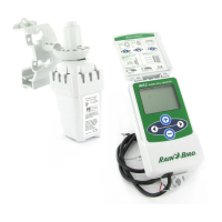
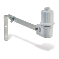
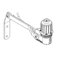
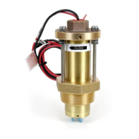
WR2 Components
Q
1 Controller Interface
Q
2 Sensor
Q
3 Battery Cassette and Lithium CR2032 Battery
Q
4 4FOTPS.PVOUJOH#SBDLFU"TTFNCMZ
Q
5 .PVOUJOH)BSEXBSF
Q
6 User’s Manual
Q
7 Quick Reference Guides
Q
8 832VJDL3FGFSFODF-BCFMT
Controller Interface - Mounting
Montaje de la interfaz del Control WR2
1
Controller Interface - Wiring
Instalación del cableado entre la interfaz de control
2
Controller Interface -
Initial Power Up
Interfaz de control -
P
uesta en marcha
inicial
3
RED ROJO - 24VAC
BLACK NEGRO - 24V
AC
WHITE BLANCO - Sensor Input (or Common) Entrada para sensore (o Common)
GREEN VERDE - S
ensor Input (or "Field") Entrada para sensore (o "Field")
1
Pair Controller Interface & Sensor
Sincronización del sensor y la interfaz del Control WR2
4
Programming Set Points
Programación de los niveles preestablecidos
5
Cable length
30" (76.2 cm)
Longitud del cableado
30" (76.2 cm)
blink
Intermitente
1
2
3
4
Rain Bird’s Wireless Rain or Rain / Freeze Sensor
Quick Reference Guide
Guía de referencia rápida
DO NOT insert battery cassette into Sensor until Controller
Interface is powered up and you are ready to “pair” the units.
No inserte las pilas en su compartimento hasta que se encienda el sensor
del interfaz del programador y este preparado para sincronizarlos.
2
!
Q
7
Q
1
Q
3
Q
2
Mounting the Controller
Interface
Choose a location near the irrigation
controller / timer.
!
The cable harness is 30 inches (76.2 cm)
long, so before mounting the device,
ensure the wires easily reach the irriga-
tion controller’s connection terminals.
t 4FMFDUBøBUTVSGBDFBEKBDFOUUPUIFJSSJHBUJPODPOUSPMMFS
t 'PSCFTUQFSGPSNBODFUIF$POUSPMMFS*OUFSGBDFTIPVMECF
JOTUBMMFEBUMFBTUöWFGFFUNBCPWFUIFHSPVOE
t It is recommended that the
$POUSPMMFS*OUFSGBDFCFJOTUBMMFE
BXBZGSPNTPVSDFTPGFMFDUSJDBM
JOUFSGFSFODFTVDIBTUSBOTGPSNFST
HFOFSBUPSTQVNQTGBOTFMFDUSJDBM
NFUFSCPYFTBOENFUBMPCKFDUTUP
maximize communication range.
t 6TFUIFNPVOUJOHIBSEXBSF
supplied. Attach the Controller
*OUFSGBDFUPUIFXBMM
Q
5
Q
4
Q
6
Q
8
NOTE: Tools needed for installation: drill, drill bit, and
Phillip's head screwdriver
1