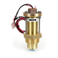
WR2 Wireless SensortXXXSBJOCJSEDPN83
3
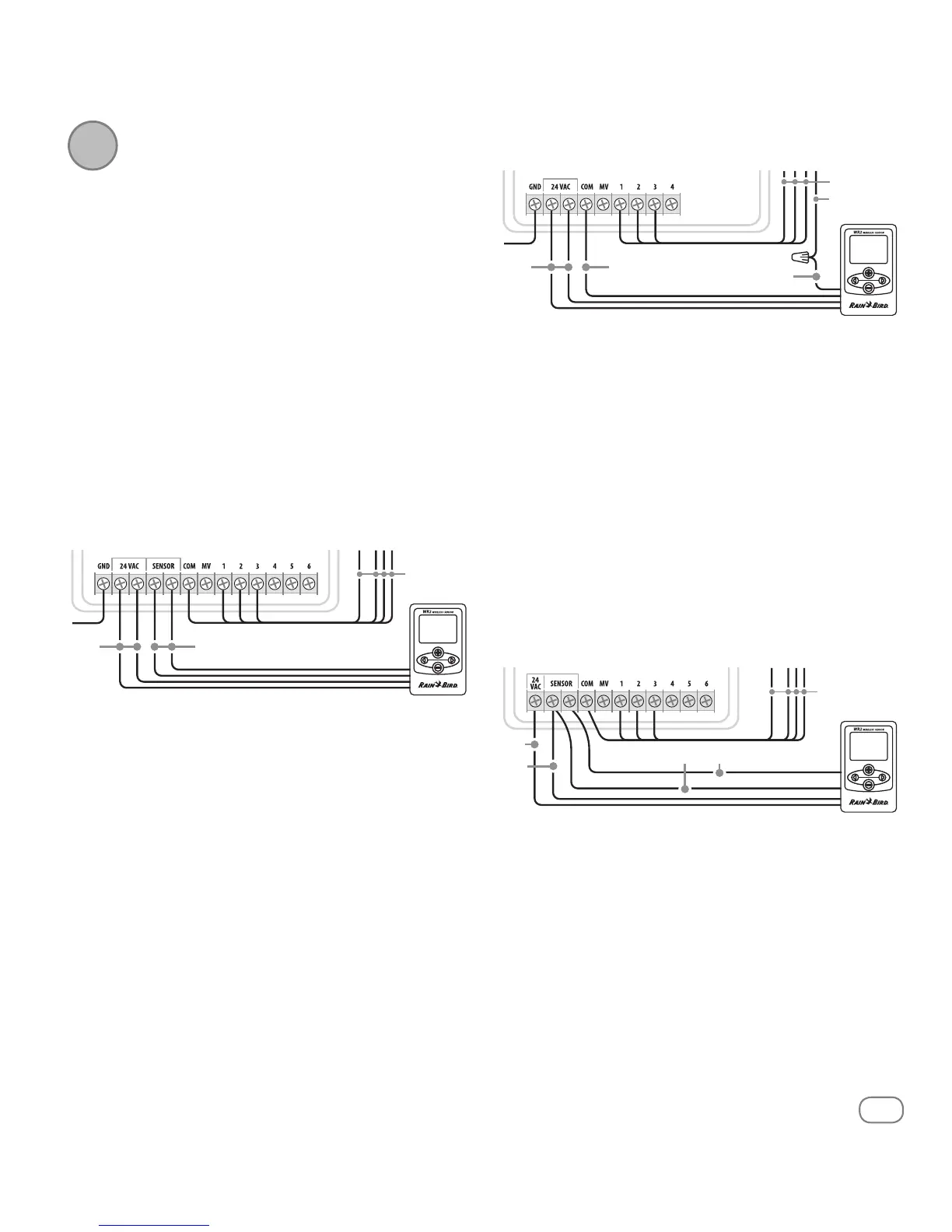
Wiring the Controller
Interface to the Irrigation
Controller
!
This unit is designed to be installed in
conjunction with 24VAC circuits only. Do
not use with 110 or 220/230 VAC circuits.
!
The Controller Interface has 4 wires that
must be connected to the irrigation
controller / timer. If your timer does not
have an internal 24VAC power source,
you will need to splice the red and black
Controller Interface wires to a 24VAC trans-
former (example: Rain Bird part number
63747301S).
Controllers with sensor inputs (with or without
pump start / master valve)
%JTDPOOFDUQPXFSUPUIFJSSJHBUJPODPOUSPMMFS
$POOFDUUIFSFEBOECMBDLXJSFTUPUIFWPMU"$QPXFS
on the irrigation controller.
*GQSFTFOUSFNPWFiKVNQFSXJSFwCFUXFFOTFOTPS
terminals.
$POOFDUUIFXIJUFBOEHSFFOXJSFTUPUIFTFOTPSJOQVUT
3FDPOOFDUQPXFSUPUIFJSSJHBUJPODPOUSPMMFS
!
Ensure the sensor switch on the irrigation
controller panel is in the active position.
Controllers with no sensor inputs (with or without
pump start / master valve)
%JTDPOOFDUQPXFSUPUIFJSSJHBUJPODPOUSPMMFS
$POOFDUUIFSFEBOECMBDLXJSFTUPUIFWPMU"$QPXFS
on the irrigation controller.
%JTDPOOFDUUIFXJSFTGSPNUIF$PNNPOUFSNJOBMPOUIF
controller.
$POOFDUUIFHSFFOXJSFUPUIFTFEJTDPOOFDUFEXJSFT
VTJOHBXJSFDPOOFDUPS
$POOFDUUIFXIJUFXJSFUPUIF$PNNPOUFSNJOBMPOUIF
controller.
3FDPOOFDUQPXFSUPUIFJSSJHBUJPODPOUSPMMFS
!
Ensure the sensor switch on the irrigation
controller panel is in the active position.
ESP-MC and ESP LX Modular Controllers
%JTDPOOFDUQPXFSUPUIFJSSJHBUJPODPOUSPMMFS
$POOFDUUIFSFEXJSFUPUIFWPMU"$UFSNJOBMPOUIF
irrigation controller.
$POOFDUUIFHSFFOBOECMBDLXJSFTUPPOFPGUIFTFOTPS
terminals.
$POOFDUUIFXIJUFXJSFUPUIFPUIFSTFOTPSUFSNJOBMPO
the controller.
3FDPOOFDUQPXFSUPUIFJSSJHBUJPODPOUSPMMFS
!
Ensure the sensor switch on the irrigation
controller panel is in the active position.
2
GREEN or
WHITE
TO VALVES
RED or
BLACK
TO VALVES
COMMON
FROM VALVES
WHITE
GREEN
RED or
BLACK
TO VALVES
WHITEGREEN
RED
BLACK