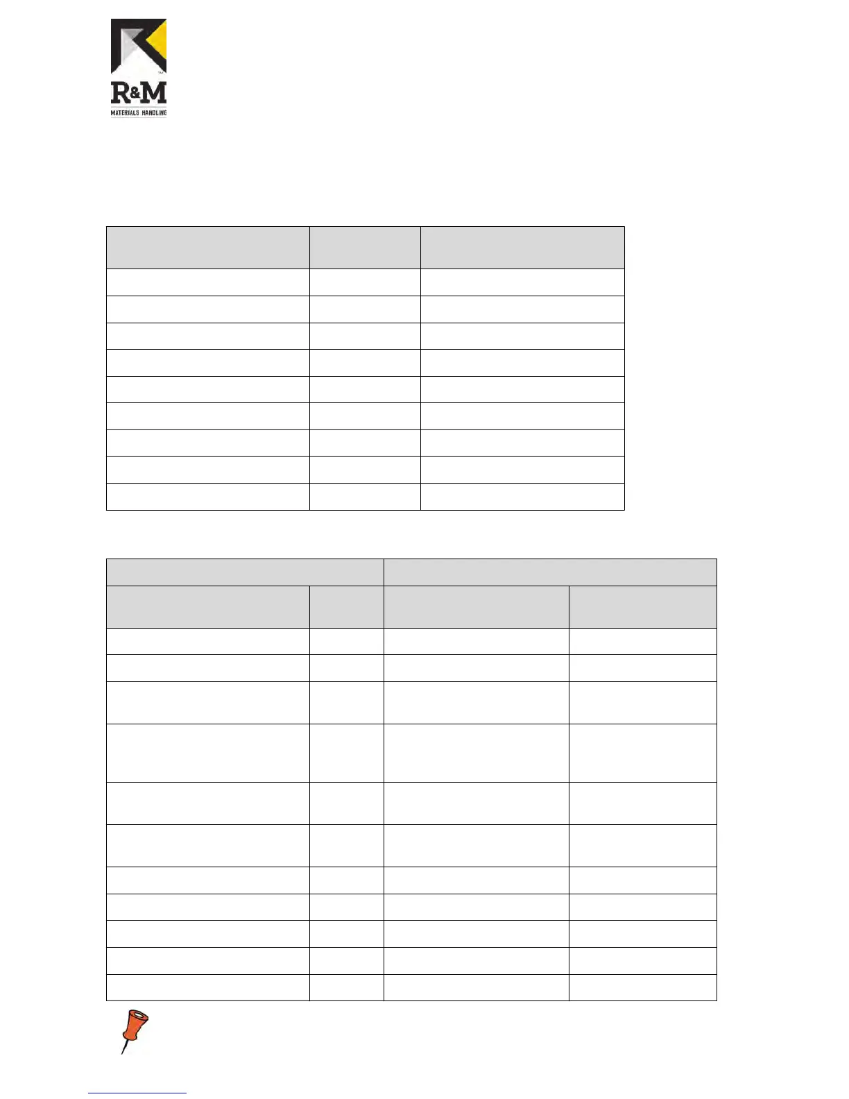
3.3 Terminal connections
Table 1. Power terminals
Description of Terminal CMX 022
Terminal X2
ControlMaster ®NXT 006
Power terminals
Power supply, phase 1 L1 L1
Power supply, phase 2 L2 L2/N
Power supply, phase 3 L3 L3
Motor supply, phase 1 U U/T1
Motor supply, phase 2 V V/T2
Motor supply, phase 3 W W/T3
Braking resistor, positive R+ R+
Braking resistor, negative R- R-
Protective earth PE PE
Table 2. Control terminals
CMX 022 ControlMaster ®NXT 006
Description of Terminal Terminal
X1
Description Control board
terminals
Drive command, direction 1 1 Drive command, direction 1 1
Drive command, direction 2 2 Drive command, direction 2 2
Speed 2 / Acceleration command 3 Speed 2 / Acceleration
command
3
Slowdown/Stop limit, direction 1 4 Common slowdown,
Slowdown/Stop limit, direction
1
4
Slowdown/Stop limit, direction 2 5 Common stop, Slowdown/
Stop limit, direction 2
5
Common DI1-5 6 Motor temperature
protection / External stop
6
Normally open relay contact 7 Common DI1-6 7
Normally open relay contact 8 Normally open relay contact 8
Empty 9 Normally open relay contact 9
Motor thermistor, T1 10
Motor Thermistor, T2 11
Terminal X1 and control board terminal pins may have different functions!
R&M Materials Handling, Inc.
4501 Gateway Boulevard
Springfield, Ohio 45502
P.: (937) 328-5100
FAX: (937) 325-5319
7/34
R&M Materials Handling, Inc. reserves the right to alter or amend the above information without notice.