4
Disconnect and mark the motor supply wires (U, V and W) with cable markers. If the CMX 022 has an
external braking
resistor, disconnect the braking resistor wires and remove the braking resistor.
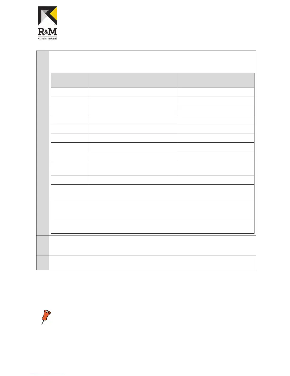
Disconnect the control wires and mark them according to the next table.
Pin in CMX 022 Connect to pin number in
ControlMaster ®NXT 006
Function
1 1 Drive command, direction 1
2 2 Drive command, direction 2
3 3 Speed 2 / Acceleration command
4 4 Slowdown/stop limit, direction 1
5 5 Slowdown/stop limit, direction 2
6 7 Common for Digital Inputs
7* 8 Normally open relay contact
8* 9 Normally open relay contact
10** Connect to OL10 signal Supply voltage for motor bi-metal
thermal protection
11** 6 Motor thermal protection
*) If there are no wires connected in pins 7 and 8 in CMX 022 , the relay is not in use and thus must
not be marked.
**)If the pins 10 and 11 are connected together, the motor thermal protection is not in use and thus
pin number 6
must be connected to OL10 signal. If there are two motors, there are two thermal
protection circuits which must be connected in series.
If there is a thermistor installed in the motor, a thermistor relay ,e.g. MSL, must be installed to
thermal protection circuit of the motor. Pin number 6 must be connected to OL10 via MSL.
5
Loosen and remove the screws (4 pcs) holding the CMX 022 . Remove the CMX 022 and the EMC-
filter from the
enclosure. Note: The old screws are self-tapping so they must not be re-used. Use the
delivered screws (part 8) instead.
6
Strip all the wires up to 10 mm. If the wires have thin strands, use wire end ferrules (Part 21) as shown
in the picture.
4.3 Control voltage front resistors
The control voltage range in the CMX 022 was 48V -
115V. If the control voltage was 230V, the front resistors
were used to decrease the control voltage to 115V or 48V. In the ControlMaster ®NXT 006 the control voltage
range is 42V - 230V. Therefore you must remove or by-pass the possible front resistors when upgrading the
CMX 022 to ControlMaster ®NXT 006 .
If the front resistors are not removed or by-passed, the control inputs on the ControlMaster
®NXT 006
frequency converter are not activated, even though voltage can be measured with
a multimeter.
4.4 By-passing the control voltage front resistor
R&M Materials Handling, Inc.
4501 Gateway Boulevard
Springfield, Ohio 45502
P.: (937) 328-5100
FAX: (937) 325-5319
11/34
R&M Materials Handling, Inc. reserves the right to alter or amend the above information without notice.