Measuring Procedure
R&S
®
RT-ZC31
24User Manual 1801.4949.02 ─ 01
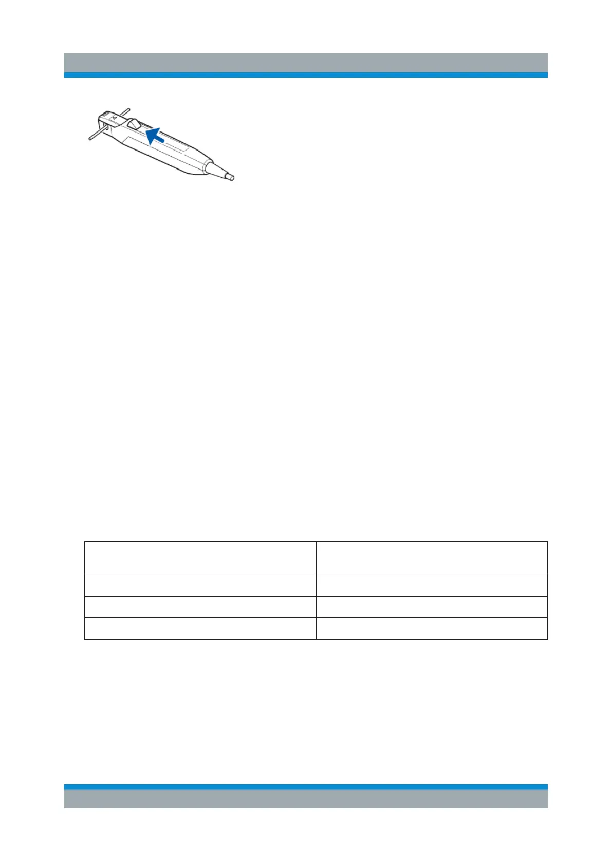
If the sensor head is not properly closed, accurate measurement is not possi-
ble.
5. Check the LEDs on the junction box:
a) POWER LED and one of RANGE LEDs light up: no error
b) OVERLOAD LED blinks rapidly: the probe has detected measurement cur-
rent in excess of the level defined for the current range. See Table 4-1.
If you use the 30 A range, immediately remove the sensor from the con-
ductor.
If you use the 0.5 A range or 5 A range, switch to a higher current range.
c) Any other LEDs light up or blinks: there is a different error. See Chap-
ter 4.2, "LED Display Errors", on page 37.
6. Press ▼ or ▲ key to choose the current range.
Choose a current range with a maximum peak current higher than the peak
value of a current to be measured.
If the peak value of the current exceeds the maximum peak current of the
chosen current range, the output waveform is saturated, preventing you from
correctly observing the current waveform.
The following table shows the recommended current ranges for each of the
levels of currents to be measured.
Electric current level Recommended current range (output
rate)
±5 A to ±50 A 30 A (0.1 V/A)
±0.5 A to ±5 A 5 A (1 V/A)
±1 mA to ±0.5 A 0.5 A (10 V/A)
Connecting the Probe to the DUT
 Loading...

