Instrument Tour
R&S
®
SMA100B
24Getting Started 1419.8620.02 ─ 07
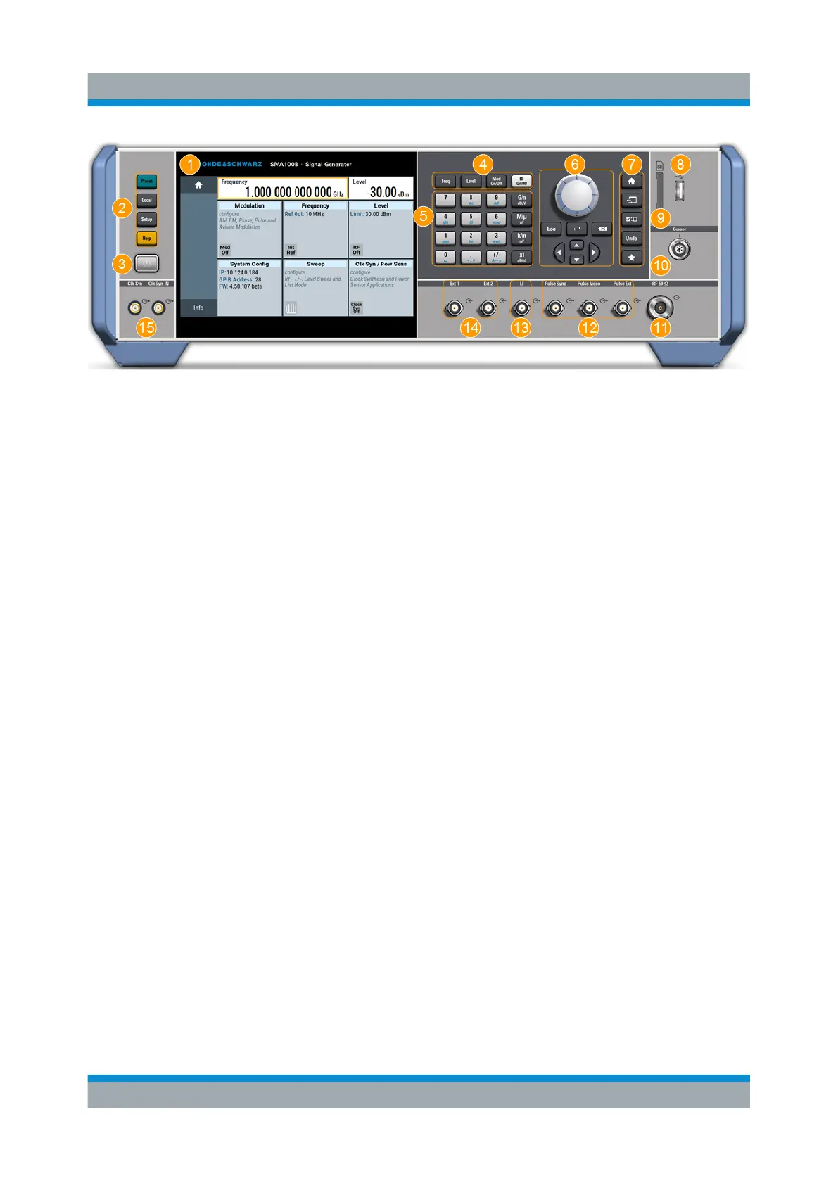
Figure 5-2: Front panel view of the R&S
SMA100B RF Signal Generator with height unit
3HU (option R&S
SMAB-B93)
1 = Touchscreen
2 = Utility keys
3 = [On/Standby]
4 = Function keys
5 = Keypad
6 = Navigation controls
7 = Display keys
8 = USB connector
9 = SD card slot
10 = Sensor connector
11 = RF output connector
12 = Pulse signal input and output connectors
13 = LF output connector
14 = Ext1/2 input connectors
15 = Clk Syn and Clk Syn N output connectors (SMA)
5.1.1 Touchscreen
The screen at the front panel is the graphical user interface. It shows the settings
dialogs and parameters, and the current configuration at a glance, see Chap-
ter 7.3, "Understanding the Display Information", on page 48.
Front Panel Tour

 Loading...

