Nozzle Body and Nozzle Control Valve Installation: Hawkeye® 2 Nozzle Body Installation 29
NOZZLE BODY AND NOZZLE CONTROL VALVE INSTALLATION
5. Attach the Wilger nozzle body to the boom.
6. Install the Hawkeye® 2 NCV to the Wilger nozzle body port closest to the wet boom tube.
7. Using the U-clip, install the ProStop-E to the previously installed adapter.
IMPORTANT: Ensure the flat surface on the U-clip is towards the ProStop-E body (tabs down). Failure to do so will result
in leaks and potential damage to components.
SPECIAL INSTALLATION INSTRUCTIONS
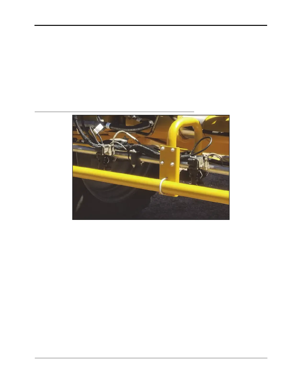
1. For the nozzle bodies on the center rack and the inner three locations of each primary boom segment, use the
modified nozzle body assembly shown below. The assembly requires the Wilger nozzle body 2-way inlet (P/N
333-0002-332), the Wilger adapter plug (P/N 333-0002-319), and Wilger end body (P/N 333-0002-325).
FIGURE 9. Completed Wilger Assembly
 Loading...