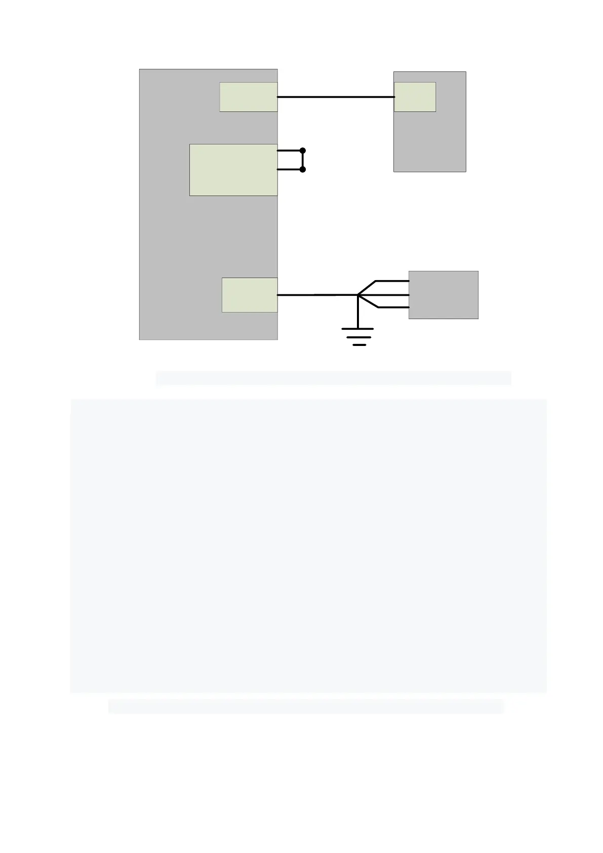
Figure 17 Internal control wiring diagram in key switch "ON" and clientware mode
Operation method:
➢ Spring the “ESTOP” knob on the front panel;
➢ Key turning “ON”;
➢ Open the laser clientware;
➢ Click “the guide laser ON” button to view the guide laser;
➢ Disabling the AD mode\external enable\internal modulation mode and external
modulation mode;
➢ Click ON “the main power ON”;
➢ Waiting “Ready”;
➢ Setting laser parameters;
➢ Click “laser ON”.
4.9.3.2 Internal/external modulation modes for power and communication in REM mode
 Loading...