Wuhan Raycus Fiber Laser Technologies Co., Ltd.
User Guide of RFL- RFL-C4000S
35
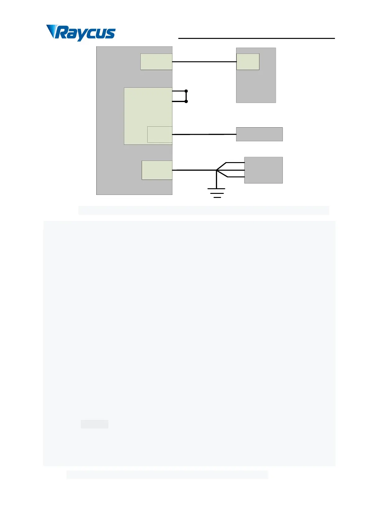
Figure 18 Wiring diagram of internal power control and external signal control in REM mode
Operation method:
➢ Spring the “ESTOP” knob on the front panel;
➢ Key turning “ON”;
➢ Shortconnect the 8 and 9 pins on the INTERFACE 24 pins (the control board is powered
on);
➢ Open the laser clientware;
➢ Click “the guide laser ON” button to view the guide laser;
➢ Disabling the AD mode and the external enable, and opening the internal modulation
mode or external modulation mode;
➢ Click ON “the main power ON”;
➢ Waiting “Ready”;
➢ Setting laser power parameters;
➢ On modulate mode set the frequency, duty cycle, and pulse width;(The laser is determined
by the 15.16 pin modulation signal and frequency and duty cycle);
➢ Modulation signal (15, and 16-pin) provide a high level to turn on the laser.
4.9.3.3 The internal/external modulation mode of the analog in REM mode
 Loading...