Wuhan Raycus Fiber Laser Technologies Co., Ltd.
User Guide of RFL-C6000S-CE
22
wires labeled L1,L2,L3and PE
L1,L2,L3-> Phase Line,
PE-> Protective Earth
L1, L2, L3->Phase wire, PE->Protective ground wire (one PE wire
is required to be connected to the ground wire of the circuit breaker,
and the other one is connected to the equipment ground wire to
ensure that the laser is fully grounded)
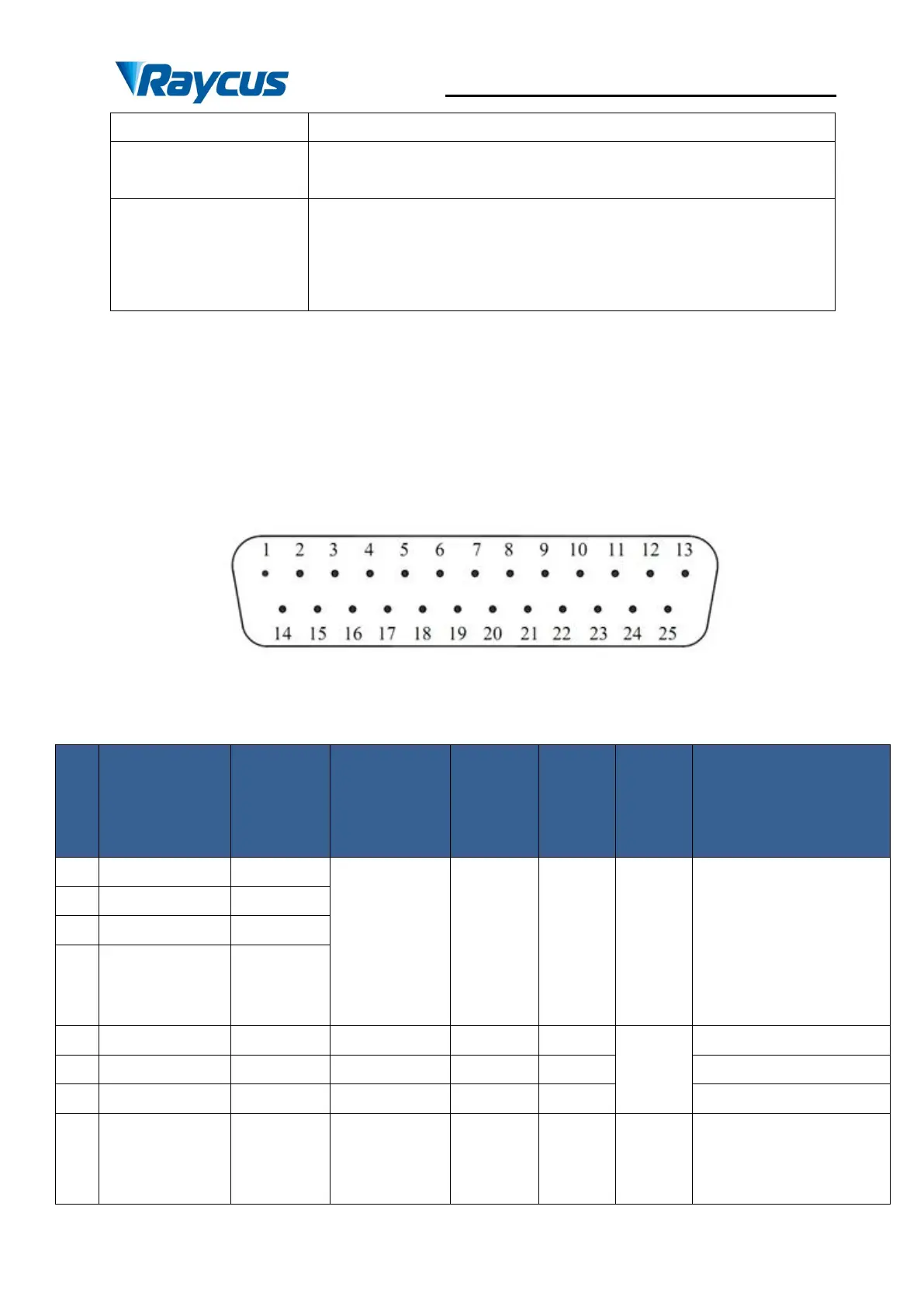
4.4 Interface Definitions
4.4.1 CTRL-INTERFACE Definitions
The CTRL-INTERFACE(DB-25) is for laser control, the designation and definition is
below:
Figure 8 Diagram of CTRL-INTERFACE
Table 7 Definitions of 24 pin Ctrl Interface
“EN954-1”
or”ISO13849-1
Cat.3PLd”.
Passive contact, not
connected to external
voltage or grounding.
Activates the internal
control system power
supply in REM mode.