1-4 DSM250 Digital Sounder Module
• Transducer detection. For safety reasons, if the transducer is
disconnected and then reconnected while the sounder is powered
on, the DSM250 does not detect that the transducer has been re-
attached. In this case, you must power down the DSM250, recon-
nect the transducer cable, and then power the sounder module
back on before it operates properly.
• Status LED. The LED on the connector panel provides valuable
status information. The LED blinks green while the module is
operating normally. If the unit detects a problem, the LED blinks
amber to indicate a warning or red for an error. The number of
times the LED blinks is a code representing the nature of the prob-
lem. Refer to Status LED on page 7-6.
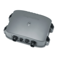
General
The DSM250 system, illustrated below, is comprised of the Dig-
ital Sounder Module, an
hsb
2
PLUS Radar, Chartplotter, or Fish-
finder display unit, transducer, and associated cables.
Figure 1-2: Basic Echosounder System using the DSM250
The DSM250 module is waterproof to CFR46 and can be installed
either above or below deck.
The unit includes connections to:
• power
• the transducer
• the display unit, via
hsb
2
• ground
hsb
2
PLUS Display Unit
D6160-1
Transducer
Digital Sounder Module
hsb
2
 Loading...