Chapter 2: Installation 2-9
Figure 2-4: Mounting the DSM250
2.6 System Connections
The rear of the display unit provides the following connection
sockets:
• Transducer connection.
• Ground connection.
• Power, for 12 V, 24 V, or 32 V DC power connection and one RF
ground (screen) connection.
• HSB, in/out connector for connecting to an
hsb
2
PLUS Series dis-
play (Chartplotter, Fishfinder or Pathfinder Radar)
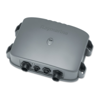
Figure 2-5: DSM250 Connector Panel
The following sections detail the connectors used when installing
the DSM250.
D6183-1
D6161-1
 Loading...