Chapter 2: Installation 2-1
Chapter 2: Installation
2.1 Introduction
This chapter provides installation instructions for your DSM250.
Basic systems, such as that in Figure 2-1 below, are explained.
Details for mounting the DSM250 and connecting the equipment
are included.
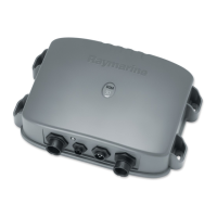
Figure 2-1: DSM250 in an Integrated System
Note: If you wish to practice using the unit before installation, con-
nect the HSB cable to a PLUS display unit and use the simulator mode
as described in Chapter 3. For power, connect a 12V or 24V DC
power supply, attaching the red wire via a quick blow 8A fuse to pos-
itive and the black wire to negative. See Section 3.6 for details.
For the system to display depth, water temperature and speed, you
must install the transducer type(s) capable of transmitting the
appropriate data.
For full functionality of the radar and chartplotter you need to pro-
vide position and heading data. For details, refer to the handbooks
for those products.
NMEA
SeaTalk
hsb
2
PLUS Display Unit
Distribution Panel
12/24V Supply
12V Supply
12V Supply
Junction
Box
GPS
Compass
Transducer
hsb
2
Digital Sounder Module
D6164-1
12/24V Supply
 Loading...