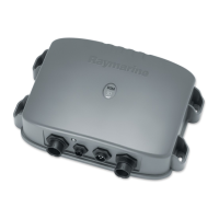
2-10 DSM250 Digital Sounder Module
DC Power Connection
The DSM250 is intended for use on ships’ DC power systems
rated from 10.7 V to 32 V.
The power connection to the unit should be made at either the out-
put of the battery isolator switch, or at a DC power distribution
panel. Raymarine recommends that power is fed directly to the
DSM250 via its own dedicated cable system and MUST be pro-
tected by a thermal circuit breaker or fuse on the red (positive)
wire, installed close to the power connection.
A 10 ft (3 m) power cable is supplied for connecting the ship’s DC
power to the unit. The power cable may be extended by up to 60 ft
(20 m) using a wire gauge of AWG 12 or greater.
DC power is connected at the three-pin POWER connector on the
unit’s connector panel. The connector (viewed from the outside)
and pin functions are shown in the following diagram and table.
f
The RED wire must be connected to the feed from the positive (+)
battery terminal and the BLACK wire to the feed from the nega-
tive (–) battery terminal. The shield wire (drain) should be con-
nected to the ship’s RF ground as described in Ground
Connection on page 2-11.
Install a quick blow 8 amp fuse on the red (positive) wire.
Figure 2-6: Power Connector
Pin No. Function Color
1 Battery positive (12/24/32 V systems) Red
2 Battery negative Black
3 Shield (drain wire) No insulation
1
2
3
D6162-1
 Loading...