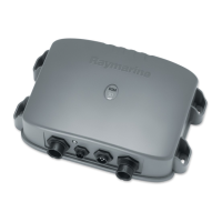
2-14 DSM250 Digital Sounder Module
Note: If your system requires both a Y-cable and a transducer exten-
sion cable, ensure that you connect the Y-cable to the sounder module
and the extension cable to the transducer.
The connector pins are shown in the following diagram, together
with the connections and wire colors; this is information is pro-
vided as an aid to fault diagnosis.
WARNING:
Do not cut the transducer cable or remove the connector.
Do not try to shorten or splice the cable. Cutting the transducer
cable will severely reduce sonar performance.
If the cable is cut, it must be replaced—it cannot be repaired.
Cutting the cable will also void the warranty.
CAUTION:
Removing the transducer cable from the rear of the DSM250
while the sounder module is powered on can cause sparks. Only
remove the transducer cable after power has been removed from
the DSM250.
Figure 2-8: DSM250 Transducer Connector
Pin
No.
Function Color
Pin
No.
Function Color
1 Speed Red 5 Speed/Temp Ground Brown
2 Temp White 6 + Depth Blue
3 Shield Drain 7 - Depth Black
4 Sense Green
5
1
2
3
4
7
6
D4850-2
 Loading...