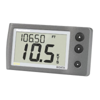
Viewingangle
Productdimensions
A
128mm(5.04in)
B
72mm(2.83in)
C55mm(2.17in)
D
18mm(0.7in)
E
17mm(0.67in)
F
30mm(1.18in)
3.6Selectingatransducerlocation
Generalspeedanddepthtransducerlocation
requirements
Whenselectingalocationforyourtransduceritis
importanttoconsideranumberoffactors.
Thetransducershouldbemountedwithintheclear
waterowareasindicatedbytheshadedareasin
theimagebelow.
1
Sailingvessel
2Planingpowervessel
3Displacementpowervessel
Eachtransducershouldalso:
•Beaheadofthepropellers(byaminimumof10%
ofthewaterlinelength).
•Beatleast150mm(6in)awayfromthekeel
(ideallyaheadofthekeelonasailingyacht).
•Beasnearaspossibletothecenterlineofthe
vessel.
•Beclearofotherthrough-hullttingsorprojections.
•Havesufcientclearanceinsidethehulltotthe
nut.
•Have100mm(4in)ofheadroomtoallowfor
withdrawal.
Note:Inadditiontotheaboverequirements,the
depthtransducermustbemountedwithin10ºof
thevertical.
20i40

 Loading...


