9
Model No.
VAC - Phase -
Hz
Minimum
Circuit
Ampacity
(A)
Breaker
Size
(A)
Min Max
5350
6350/6350HC
8350/8350HC
10355
Table B. Electrical Power Requirements
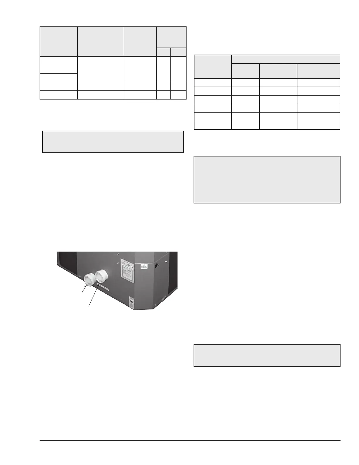
6. WATER CONNECTIONS
CAUTION: The heater inlet and outlet connections
are NOT interchangeable. They must be connected as
instructed below.
page15
WATER IN
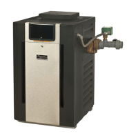
Figure 4. Water Connections
7. PRESSURE DROP
Table C
Flow
gpm (lpm)
Pressure Drop PSI (kPa)
5350 6350/6350HC
8350/8350HC/
8360
Table C. Pressure Drop Across Heater
A
WARNING: Install a check valve and/or a Hartford
loop AFTER the heater and BEFORE any chlorinating
devices. Install any automatic chemical feeders AFTER
the heater. Improper installation of any type of automatic
chemical feeders can result in serious damage to, or
premature failure of the heater. Such damage will not be
covered under warranty.
8. CONTROLS & INDICATOR
LAMPS (ANALOG
MODELS)
page 11
Water Pressure Switch
Water Temperature Control
NOTE: The heater will not run when the Remote position
is selected on the Pool/Spa selector switch and there is
no remote control system attached.
Defrost Switch
Delay Time