112
16. using only water, wash the inside
of the combustion chamber, detail
“H” in Figure 15-7. The water, will
drain into the condensate drain;
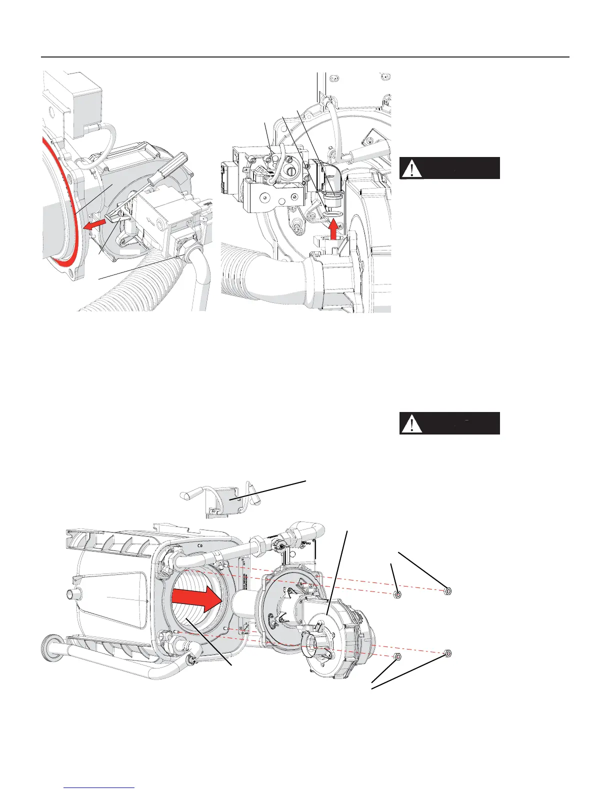
17. replace gasket “G” as per Figure
15-5 (Part number for this gasket is
60703047).
WARNING!!!
Take care
attention to the gasket
“G” (Figure 15-5) during
reassemble. When fi nish,
perform on it a leakage test
with the burner fi ring. Always
use an approved leak detection
method. Failure to comply with
this warning can cause fi re,
extensive property damage,
severe personal injury or death!
18. reassemble the components by
proceeding in reverse order. Taking
care attention in the reinstalling
of gasket between nut “H” of
Figure 15-5 and of the o-ring “L”
of Figure 15-6. These must be in
good condition. If not they must be
replaced with some new one;
19. open the manual gas shutoff valve;
20. check that there are no gas leaks.
WARNING!!!
Never use
an open fl ame to test for gas
leaks. Always use an approved
leak detection method. Failure
to comply with this warning can
cause fi re, extensive property
damage, severe personal injury
or death!
21. restore electrical power to the
heater;
A
H
G
020010.01.020
Figure 15-5 Nut and spring
that fi xes the gas valve
L
C
B
020010.01.021
Figure 15-6 Remove the gas
valve
H
A
C
B
B
020009.01.011
Figure 15-7 Remove the fan burner assembly
15 - MAINTENANCE

 Loading...