35
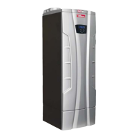
Figure 6-3 Install eyebolt to lift the appliance
6 - INSTALLATION - Mounting the heater
A
020010.01.009
B
020012.01.008
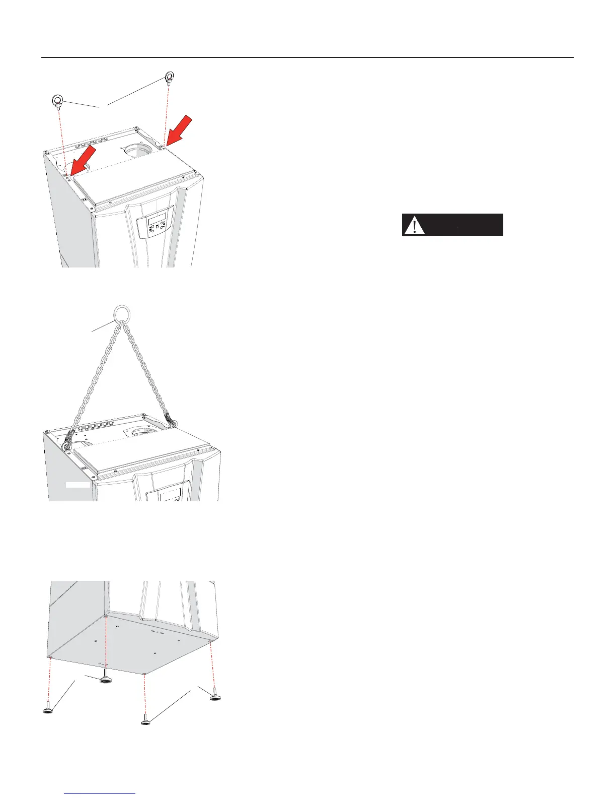
Figure 6-4 Correct way to lift the appliance
Figure 6-5 Install leveling feet
A
A
020010.01.013
4. take the two factory supplied
eyebolts “A” (Figure 6-3) and install
them on the upper side of the
heater
(see Figure 6-3);
5. Using a proper equipment (check
the weight of the unit in Section
16), and lift the unit from the wood
pallet and move it to the installation
location;
6. Install the leveling feet and plumb
the unit accordingly (see Figure
6-5);
WARNING!!!
The fl oor
must be capable of supporting
the weight (see Section 16)
of the unit or the same unit
and building may be damaged
causing severe personal injury,
death, or substantial property
damage.
6.3 - Dimensions
Figures from 6-6 to 6-8 report all
dimensions of each heater model.

 Loading...