113
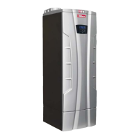
A = Left ignition electrode
B = Right ignition electrode
C = Flame detection electrode
Figure 15-8 Positioning electrodes on burner
(Use a hand caliper to verify the distances)
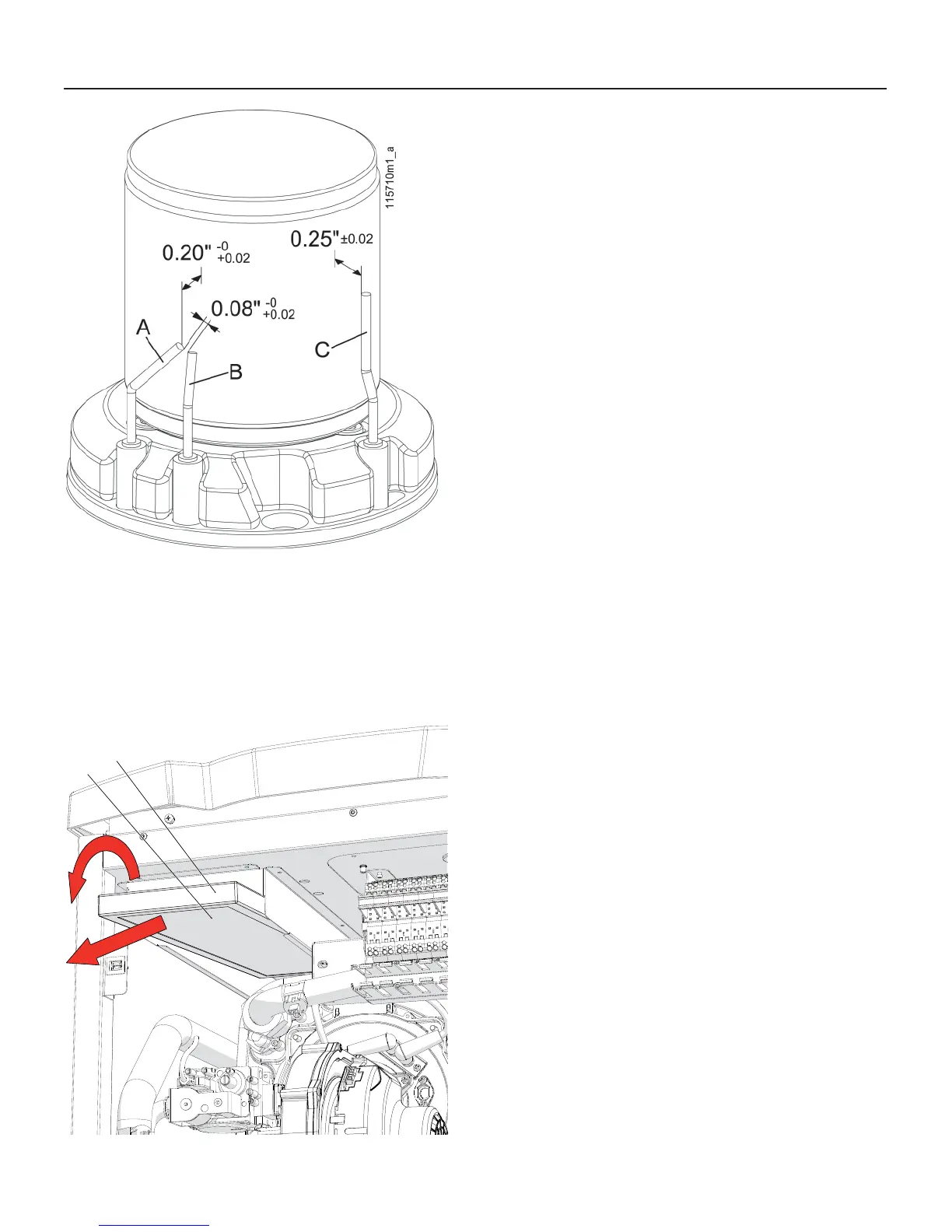
B
A
020010.01.018
Figure 15-9 Remove the air fi lter “B”
15.4 - Correct
positioning of
the ignition and
fl ame detection
electrodes
For the heater to work properly the
electrodes must be positioned as
shown in Figure 15-8:
the distance between the ignition
electrodes “A” and “B”, must be
between 0.08 in (2 mm), and 0.10
in (2.5 mm);
the distance of the ignition
electrodes to the burner surface
must be between 0.20 in (5.0 mm),
and 0.22 in (5.5 mm);
the distance of the fl ame detection
electrode to the burner surface
must be between 0.23 in (6.0 mm),
and 0.27 in (7.0 mm).
NOTICE! To insure correct functioning
of heater the distances listed above
shall be verifi ed very carefully also
using a hand caliper.
15.5 - Clean the air
fi lter
For the heater to work properly the air
fi lte must be clean. A dirty air fi lter can
cause a power input reduction of the
unit, resulting in system malfunctions.
Operate as follow in order to clean the
air fi lter:
1. follow the steps in Section 15.2
to gain access to the internal
components;
2. pull down with a rotation the air
fi lter “B” as per Figure 15-9
3. pull back the air fi lter and remove it
from the unit.
4. with compressed air, clean the
surface of the air fi lter;
5. reassemble the air fi lter
15 - MAINTENANCE

 Loading...