91
13.3 - Confi rming the
heater’s gas type
The type of gas and the gas supply
pressure that the heater is set up for is
listed on the rating label.
The heater can operate using one of the
following two gases:
NATURAL GAS
Maximum supply pressure = 13 in.W.C.
(33.0 mbar).
Minimum supply pressure = 3 in.W.C.
(7.6 mbar).
LP Gas
Maximum supply pressure = 13 in.W.C.
(33.0 mbar).
Minimum supply pressure = 3 in.W.C.
(7.6 mbar).
13.4 - Gas type
conversion
If the gas available at the installation site
is not the type the heater is confi gured
to use, the heater must be converted.
Special conversion kits are available for
this purpose inside the heater. Follow
instruction on Sections 12.6 and 12.7.
WARNING!!!
Conversion
of the heater to use another type
of gas must be carried out by a
qualifi ed technician. Improper
conversion of the heater could
result in a fi re or an explosion
causing severe personal injury or
death!
13.5 - Start-up
13.5.1 - Start-up of the IB
boiler
1. Open the manual gas shut off valve
(Figure 12-1).
2. Switch the on/off power switch, item
“T” in Figure 14-1, to “on”.
3. The heater will fi re only when the
room thermostat calls for heat and
the heating temperature settings
is higher than the actual supply
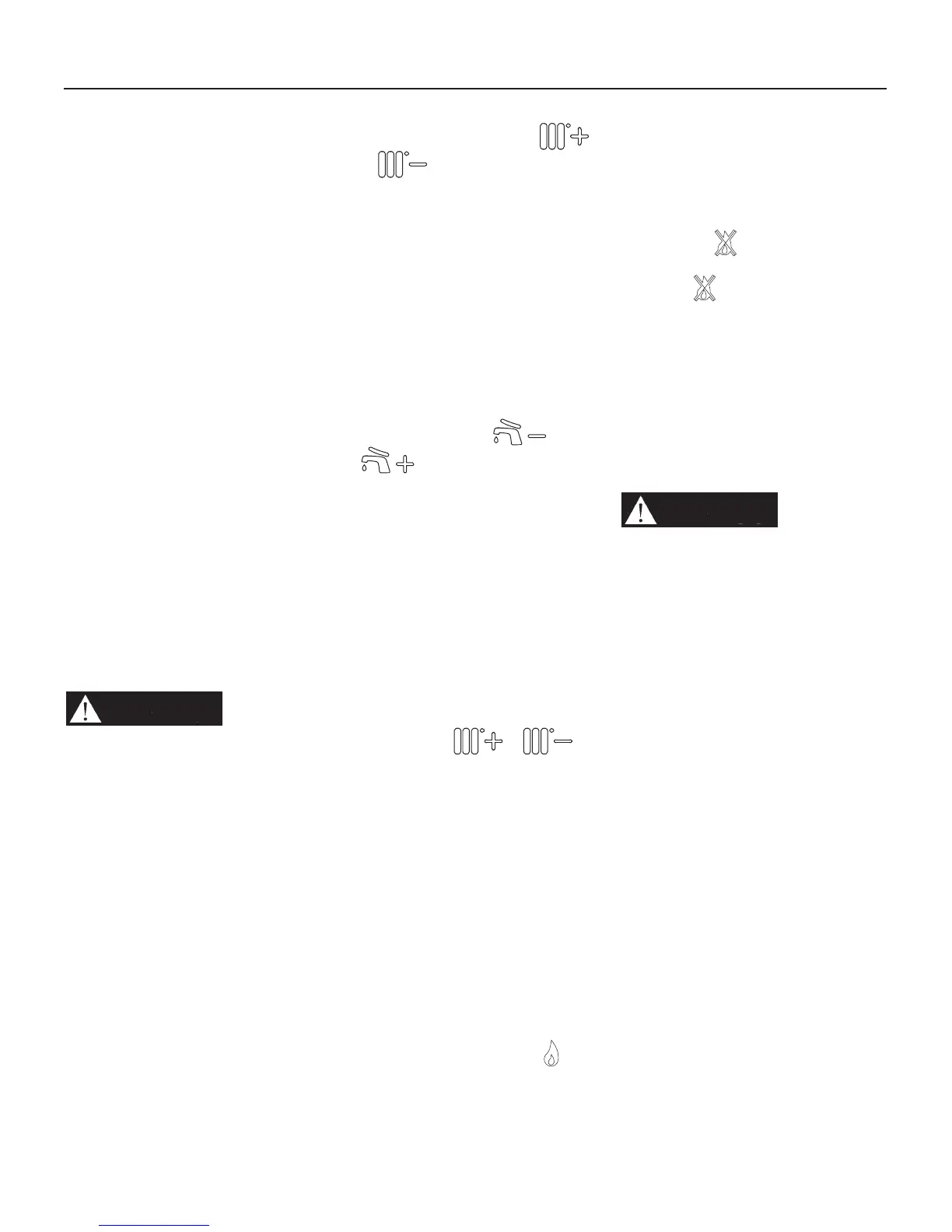
temperature. Press buttons
or
to select the desired
heating temperature. If the external
temperature sensor is connected
(See Section 10.1.3), check that the
calculated temperature (See Section
14.13, parameter 1012 or parameter
1107 for heater models 399 to 1000)
is higher than the actual heater
temperature and that the outdoor
temperature (See Section 14.13,
parameter 1004) is lower than “warm
wheather shut down temperature”,
(parameter 2020 into Section 14.14).
4. If the heater is connected to an
indirect water heater (See Section
7.2.6) press buttons and
to select the desired
domestic hot water temperature.
5. If the display gives a Low water fl ow
error (see Section 14.17), repeat the
air purging operations.
13.5.1 - Start-up of the IW
water heater
1. Open the manual gas shut off valve
(Figure 12-1).
2. Switch the on/off power switch, item
“T” in Figure 14-1, to “on”.
3. The heater will fi re only when the
supply temperature settings is higher
than the actual supply temperature.
Press buttons or to
select the desired supply temperature.
4. If the display gives a Low water fl ow
error (see Section 14.17), repeat the
air purging operations.
13.6 - Ignition control
testing
After placing the heater in operation, the
ignition control’s safety shutoff function
must be tested as follow:
1. turn the power switch (item “T” in
Figure 14-1) to on;
2. follow Section 13.5 to create a call for
heat;
3. wait a few minutes for the burner to
light-up as indicated by icon . On
units model 399 and 500, wait until
icons and are present on the
display. On units model 750 wait until
icons
and are displayed.
On units model 1000 wait until icons
and are displayed.
4. close the manual gas shutoff valve,
see Figure 11-1;
5. after 3 minutes, the display must show
Loc 01 and or, on models 399 to
1000 all burners icons will blinking and
the icon is displayed;
NOTICE! On unit models 750 and 1000,
because they have 3 and 4 burners,
the time to see all burners icons
blinking, can arrive at 15 - 20 minutes
6. open the manual gas shutoff valve,
see Figure 12-1;
7. verify your gas meter. Gas fl ow must
be zero.
WARNING!!!
If gas fl ow
occurs, close the manual gas
shutoff valve and troubleshoot
the system to determine why
there is gas fl ow when the gas
valve should be deenergized.
Do not operate the heater until
the problem is resolved or a fi re
or explosion causing property
damage, personal injury or loss
of life may occur!
13 - START-UP