92
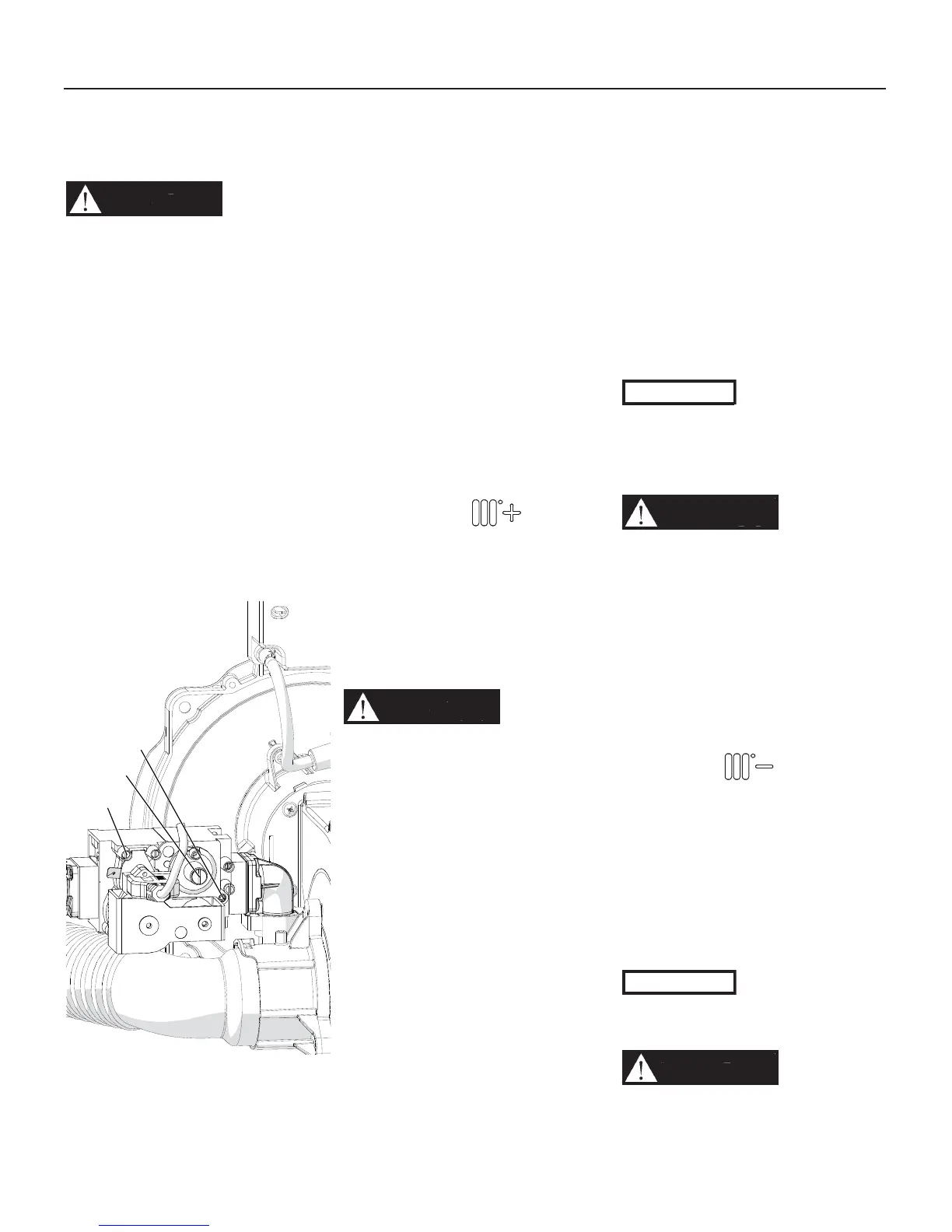
Figure 13-1 Gas valve
D - Inlet gas pressure
probe
E - CO2 adjusting screw
F - Factory adjusted
regulator (Should never
be touched)
13.7 - Gas supply
pressure checking
WARNING!!!
DO NOT
adjust or attempt to measure
gas valve outlet pressure.
The
gas valve is factory-set for the
correct outlet pressure. This
setting is suitable for natural
gas and propane, requiring no
fi eld adjustment. Attempting to
alter or measure the gas valve
outlet pressure could result
in damage to the gas valve,
causing
excessive levels of
carbon monoxide, which can
result in severe personal injury
or death!
Check the gas supply pressure by
following the steps below:
1. close the manual gas shut-off
valve, Figure 12-1;
2. follow the steps in Section 15.2 to
remove the front cover;
3. turn the screw in pressure port “D”
shown in Figure 13-1 three turns
counterclockwise;
4. connect a manometer with
graduations of at least 0.1 in.W.C.
(0.25 mbar) to the inlet gas port
“D” shown in Figure 13-1 (on unit
model 399 to 1000, choose the
pressure port “D” from any gas
valve present).
5. open the manual gas shut off valve,
Figure 12-1;
6. check that the gas supply pressure
does not exceed 13 in.W.C. If the
gas supply pressure is higher than
13 in.W.C. adjust the upstream gas
pressure regulator to bring the gas
supply pressure between 12”WC
and 13”WC;
7. turn the power switch to on and
generate a heat demand by
pressing button to its
maximum setting. Also ensure that
the room thermostat is calling for
heat and operate downstream the
13 - START-UP
E
D
F
020010.01.022
unit to verifi y the system is able to
dissipate all heat generated.
8. give 3 minutes to each heat
exchanger to reach the maximum
capacity. Check parameters 1120
up to 1123 (Section 14.13) to see
the modulating level. Must be at
100% per each heat exchanger.
9. check the manometer to make sure
the gas supply pressure does not
drop below 3 in.W.C. (7.6 mbar).
If the gas supply pressure is lower
than 3 in.W.C. means that your
inlet gas line or your gas pressure
regulator are not correctly sized;
CAUTION!!!
Do not attempt
to adjust your upstream gas
pressure regulator. This
was already adjusted for the
maximum inlet gas pressure.
WARNING!!!
DO NOT
adjust the screws “E” and/or
“F” (Figure 13-1). These screws
are factory-set for the correct
gas fl ow and outlet pressure.
Attempting to alter the gas
valve setting could result in
damage to the valve, causing
potential severe personal
injury, death, or substantial
property damage.
After verifying the correct gas
pressures:
1. push button up to see OFF
word on Display to bring the unit
into stand-by;
2. close the manual gas shut-off
valve, Figure 12-1;
2. disconnect the manometer;
3. turn the screw in pressure
connection “D” in Figure 13-1,
clockwise until snug;
4 check pressure port “D” (Figure 13-
1) for any gas leaks.
CAUTION!!!
Never force the
pressure connection screw or
the gas valve will be damaged!
WARNING!!!
Never use an
open fl ame to check for gas
leaks, a fi re or an explosion
could result causing severe
personal injury or death!
WARNING!!!
DO NOT
adjust the screws “E” and/or
“F” (Figure 13-1). These screws
are factory-set for the correct
gas fl ow and outlet pressure.
Attempting to alter the gas
valve setting could result in
damage to the valve, causing
potential severe personal
injury, death, or substantial
property damage.

 Loading...