116
15 - MAINTENANCE
15.8 - How to move a
control board
Multiburner units models 399 to 1000 are
confi gured to be drived by one control board
(named Burner 1 (Master)). On this board are
connected all external devices such as: room
thermostat, outdoor sensor, pumps commands,
LWCO, and some internal safety devices such
as: blocked drain magnetic switch, fl ue blocked
pressure switch, etc.
If this Burner 1 control board fail, the complete
unit stops to work. If installer don’t have a
replacement part, it can replace the Burner 1
control board for another installed on the unit
and reactivate it.
To do so, operate as follow:
1. turn off the electrical power;
2. follow the steps in Section 15.2 to remove
the cover and gain access to the internal
components;
3. disconnect plug “B” (plug coming from
display) from plug “A” (plug coming from
“Burner 1 (Master)”);
4. disconnect all other plugs from Burner 1
(Master) control board;
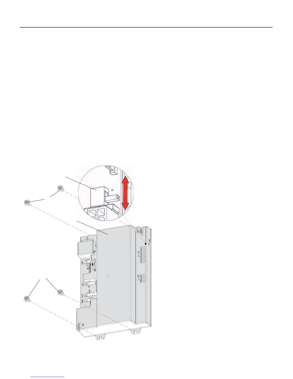
5. loosen screws “D” (see Figure 15-13) of the
Burner 1 (Master) control board;
6. remove screws “C” from the Burner 1
(Master) control board;
7. remove the Burner 1 (Master) control board
from the appliance;
8. following step 3 to 7 above to remove the
board located in the lower side of the unit;
9. install this last control board in the site where
there where the Burner 1 (Master) control
board;
10. reconnect all plugs to this board;
11. move “Switch S4” as per Figure 15-13, from
OFF position to ON position;
12. take kare attention that all connections of the
removed board are not in short circuit or in
dangerous position;
13. electrically insulate each one of these plugs;
14.close the external jacket of the unit;
15. turn the electrical power on to the unit;
16. gain access to the Factory menu, follow
Section 19 and set all parameters follow
column “Burner 1 (Master)” (take care
attention to parameter 3050. Because you
are moving a board to the master, the 3050
value must be reduced of one unit respect the
stated).
17. shut off electrical power to the unit;
18. shut on the power to the unit. Now the new
Burner 1 control board should drive the unit
correctly.
SWITCH S4
A
D
C
020009.01.010
Figure 15-13 Control board “A” and Modbus board “B”
ON position
OFF position

 Loading...