44
8.1 - IW Water
heaters’ water
connections
The water heater comes with the
connections shown in Figures 6-6, 6-7
or 6-8.
8.2 - Hot and Cold
water piping
The water heater is equipped with ASME
safety P-T relief valves set at 125 PSI (8,6
bar) 210°F (99°C). However, this water
heater can be equipped with P-T relief
valves set at maximum 160 PSI (11.2
bar) 210°F (99°C) that is the maximum
working pressure - temperature.
CAUTION!!!
All water system
piping must be installed in
accordance with the ANSI/ASME
Boiler and Pressure Vessel Code,
Section IV. All applicable local
codes and ordinances must also
be followed.
CAUTION!!!
Before connecting
the water heater to the system this
last must be thoroughly fl ushed
to remove sediment, fl ux, fi lings
and other foreign matter. The
heat exchanger can be damaged
by build-up or corrosion due to
sediment.
CAUTION!!!
This water heater
can supply water at a temperature
up to 203°F (95°C) (setup of the
safety high limit thermostat) and
pressure of 160 PSI (11,2 bar)
(maximum setup of the relief
valve). If the hot water system
is built with materials not able
to resist to this temperature
and pressure, contractor must
supply and install a device that
will shut-off the appliance before
the system material’s maximum
operating temperature and
pressure are met.
CAUTION!!!
Do not use this
heater to directly heat swimming
pool or spa water.
8.2.1 - Near water heater
piping components
Water heater system piping MUST be
sized considering the pressure drops
of the water heater (see Figure 7-3),
pipings and storage tank.
Reducing the pipe size can restrict
the fl ow rate through the water heater,
causing poor system performance.
Basic steps are listed below along
with illustrations on Figures 8-5 and
8-6, which will guide you through the
installation of the water heater.
1. Connect the cold water supply to
the inlet side of the water heater.
2. Connect the hot water supply to the
outlet side of the water heater.
3. Install a backfl ow preventer (fi eld
supplied) on the cold feed make-up
water line.
4. Install a fi eld supplied pump as
shown in Figures 8-5 and 8-6.
5. Install a fi eld supplied expansion
tank on the cold water inlet.
Consult the tank manufacturer’s
instruction for specifi c information
relating to tank installation. Size
the expansion tank for the required
system volume and capacity.
6. Install a drain valve at the lowest
point of the system.
7. Pipe the discharge outlet of any
Pressure and temperature relief
valve following Section 8.2.2.
The temperature and pressure
relief valve is sized to ASME
specifi cations. Storage tanks may
require additional valves depending
on local codes.
8. Water heater isolation valves: Field
supplied. Install isolation valves
as shown on fi gures 8-5 and 8-6.
Full port ball valves are required.
Failure to use full port ball valves
could result in a restricted fl ow rate
through the water heater.
9. Anti-scald mixing valve: Field
supplied. Install an anti-scald
mixing valve as shown on fi gures
8-5 and 8-6. An Anti scald mixing
valve is recommended when
storing domestic hot water above
115°F.
10. Unions: Field supplied. Install
Unios as shown on Figures 8-5
and 8-6, recommended for unit
serviceability.
11. Tank sensor: Factory supplied
on water heater. The tank sensor
MUST be installed in the lower
25% of the storage tank to achieve
proper operation.
12. Filter: Field supplied. Install a
fi lter or equivalent multipurpose
strainer at the cold water inlet
connection of the water heater to
remove system particles from older
hydronic systems and protect newer
systems.
Install the heater so the gas ignition
system components are protected
from water (dripping, spraying, etc.),
during appliance operation for basic
service or circulator, valves and other
parts replacement.
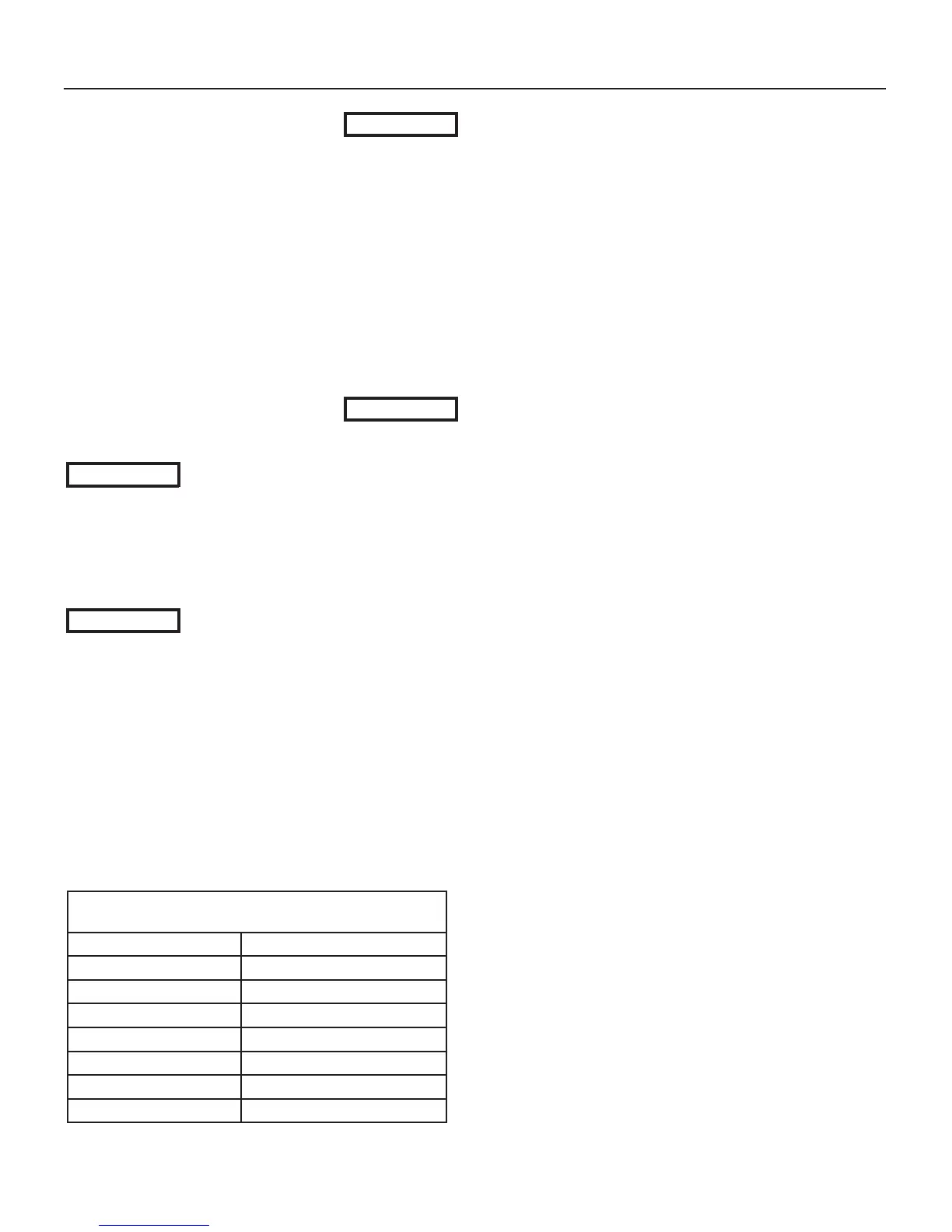
APPROXIMATE TIME / TEMPERATURE
RELATIONSHIPS IN SCALDS
120°F (49°C) More than 5 minutes
125°F (51°C) 1,5 to 2 minutes
130°F (54°C) About 30 seconds
135°F (57°C) About 10 seconds
140°F (60°C) Less than 5 seconds
145°F (63°C) Less than 3 seconds
150°F (65°C) About 1,5 seconds
155°F (68°C) About 1 second
Figure 8-1 Time / temperature scalds
8 - INSTALLATION - IW water connections

 Loading...