111
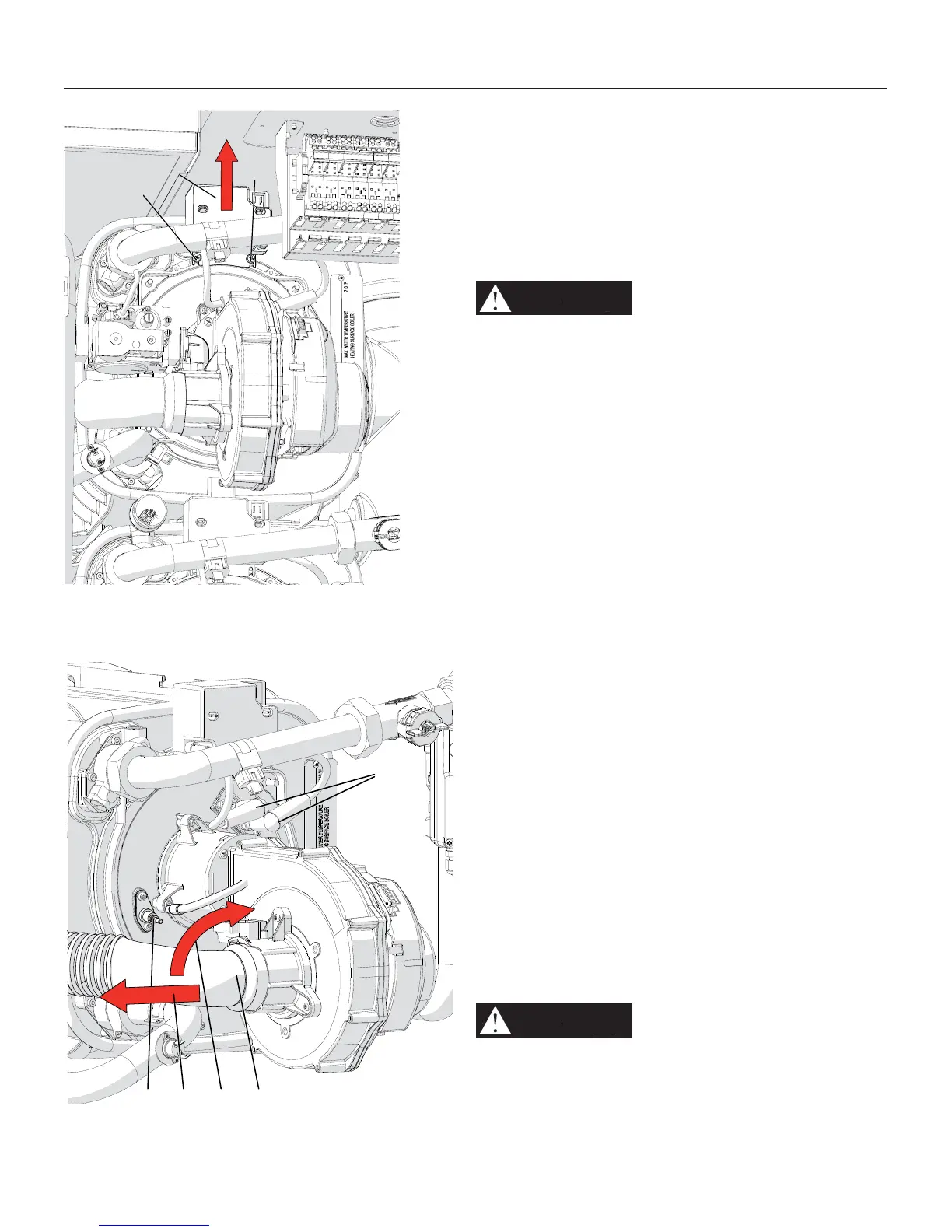
Figure 15-4 Remove the air inlet silencer
15 - MAINTENANCE
15.3 - Cleaning the burner and
primary heat exchanger, fl ue
gas side
Burner and primary heat exchanger must be checked every
year and cleaned if required. To correctly clean the burner
and the fl ue gas side of the heat exchanger follow the steps
below:
WARNING!!!
Before proceeding to the next
step, verify that the electrical supply to the heater,
and any other electrical supply near the heater,
is off. Verify that the manual gas shut off valve is
closed. Failure to comply with this warning can
cause extensive property damage, severe personal
injury or death!
1. follow the steps in Section 15.2 to gain access to the
internal components;
2. for units 399 up to 1000, prepare a suitable cover for
the burner units below your actual site (if any) so that no
dirt, water, or other foreign objects can fall into above the
same below burner unit;
3. loosen scres “D” (Figure 15-3) and move up the spark
generator “A” (Figure 15-3);
4. disconnect the two wires “D” (Figure 15-4) from the
ignition electrodes and the wire “E” (Figure 15-4) from the
fl ame detection electrode;
5. rotate the air inlet silencer “B” (Figure 15-4) in the up
direction;
6. pull in the left direction “C” (Figure 15-4) the air inlet
silencer and remove it from the fan;
7. unscrew nut “H” (Figure 15-5). Take care attention to the
gasket between nut “H” (Figure 15-5) and the gas valve.
8. take away the spring “A” as per Figure 15-5. Help
yourself with a screwdriver;
9. remove the electrical plug from the gas valve;
10. Remove the gas valve from its position (see Figure 15-
6). Take care attention to the o-ring “L” of Figure 15-6;
11. unscrew the four nuts “B” in Figure 15-7;
12. remove the entire fan - burner assembly, detail “C” in
Figure 15-7;
13. use a cylindrical brush with plastic bristles to clean the
inside of the combustion chamber, detail “H” in Figure
15-7;
14. use a vacuum cleaner to remove any unburned residue
from the combustion chamber “H” in Figure 15-7;
15. using the same vacuum cleaner, clean the surfaces of
the burner and around the electrodes;
WARNING!!!
while performing the next step,
carefully wash only the inside of the combustion
chamber “H” of Figure 15-7, and do not get
water on the outside of the combustion chamber
opening. Failure to comply with this warning can
cause extensive property damage, severe personal
injury or death!
D
D
A
020009.01.012
D
BE C A
020009.01.014
Figure 15-3 Remove the spark generator

 Loading...