59
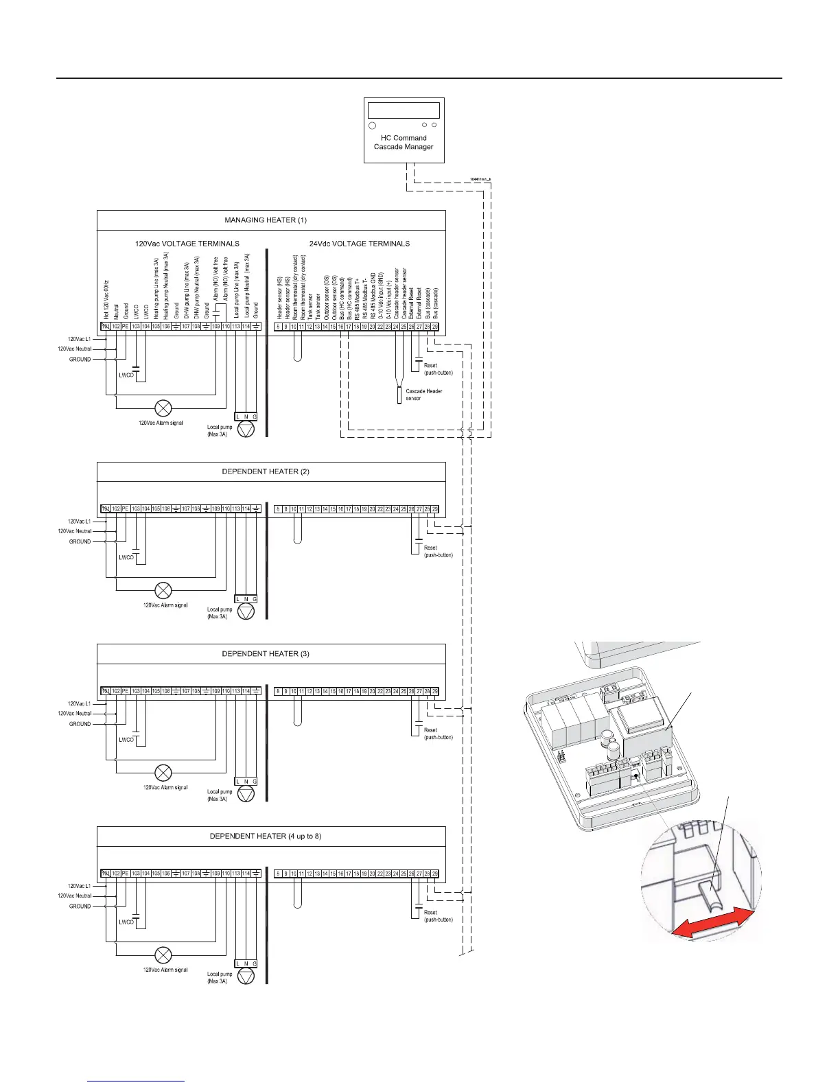
Figure 10-7 Electrical customer connection for
Cascade (boilers or water heaters)
10 - INSTALLATION - Electrical connections
10.4 - Connecting
the heater in
cascade
To connect the heater in cascade
you have to follow the electrical
connections as per Figure 10-7.
A maximum of 8 heaters can be
connected in cascade (Figure 10-7
shows the connection of 4 heaters).
When the electrical connection
is placed, to activate the BUS
communication to the HC command,
follow the next steps:
1. - Gain access to internal part of the
heater (see Section 15.2)
2. - Move selector S4 of the Burner 1
(Master) board in the off position
(see Figure 15-13 to identify
the selector S4 of the Burner 1
(Master) board.
3. - Move selector S4 of the MODBUS
interface (item 13 on Figures 3-3,
3-5, and 3-8), in the ON position
(see Figure 10-8).
The HC Command, that is the
cascade manager, is supplied on
demand.
For water, gas, fl ue exhaust
and air intake connections, ask
for conceptual drawings to the
manufacturer/distributor/agent.
020009.01.019
SWITCH S4
B
ON
position
OFF
position
Figure 10-8 MODBUS board
and “Switch S4”

 Loading...