40
7 - INSTALLATION - IB boiler water connections
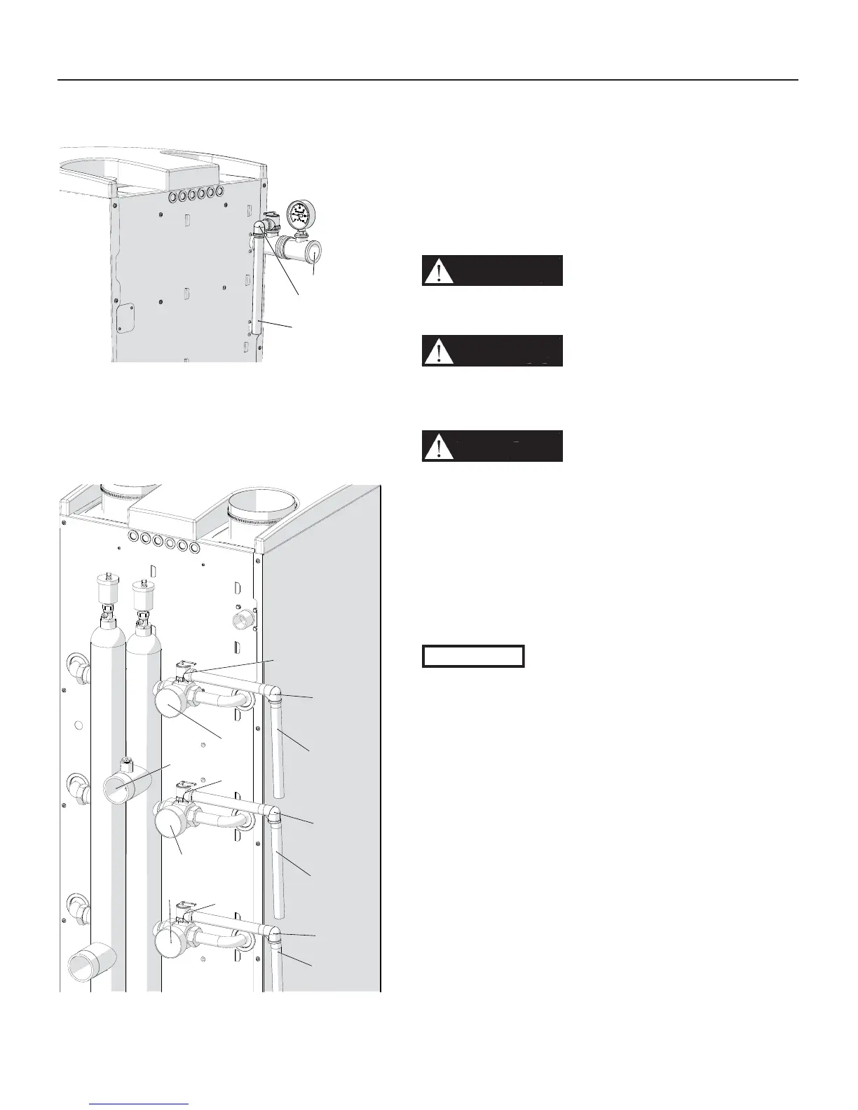
Key to Figures 7-1 and 7-2
E = Safety relief valve
F = Temperature and pressure gauge
G = Elbow (Field provided)
H = Relief valve discharge piping (Field provided)
L = Heating supply connection
7.2.2 - Relief valve
This boiler is supplied with a Safety Relief valve installed
in accordance with the ANSI/ASME Boiler and Pressure
Vessel Code, Section IV. Pipe the relief valve discharge like
on Figures 7-1 or 7-2 to prevent scalding in the event of a
discharge.
Pipe the discharge of the safety relief valve to a suitable
drain. Provide piping that is the same size as the safety relief
valve outlet.
WARNING!!!
Failure to properly pipe the relief
valve discharge can result in scalding of individuals
and animals.
WARNING!!!
Never install any type of valve
between the boiler and the relief valve or an
explosion causing extensive property damage,
severe personal injury or death may occur!
WARNING!!!
Never block or plug the outlet
of the safety relief valve or an explosion causing
extensive property damage, severe personal injury
or death may occur!
7.2.3 - Expansion Tank and Makeup
Water
Install an expansion tank. Ensure the expansion tank is
properly sized for the boiler volume (See Section 16, header
“Content of water”) and the system volume, temperature and
pressure.
CAUTION!!!
Undersized expansion tanks will cause
system water to be lost through the pressure relief
valve and cause additional makeup water to be
added to the system. Eventual boiler failure can
result due to this excessive makeup water addition,
compromising the functionality of the unit.
The expansion tank must be located as shown in Figures
7-4 and 7-5 when using a primary/secondary piping
arrangement or as per recognized design methods. Refer to
the expansion tank manufacturer instructions for additional
installation details.
Connect the expansion tank to an air separator only if the air
separator is located on the suction side (inlet) of the system
circulator.
Always locate and install the system fi ll connection at the
same location as the expansion tank connection to the
system.
H
G
L
010.01.008
F
E
H
L
F
E
G
H
F
E
G
H
G
020009.01.009
Figure 7-1 Piping the relief valve
discharge on models 199
Figure 7-2 Piping the relief valve
discharge on models 399 up to 1000

 Loading...