43
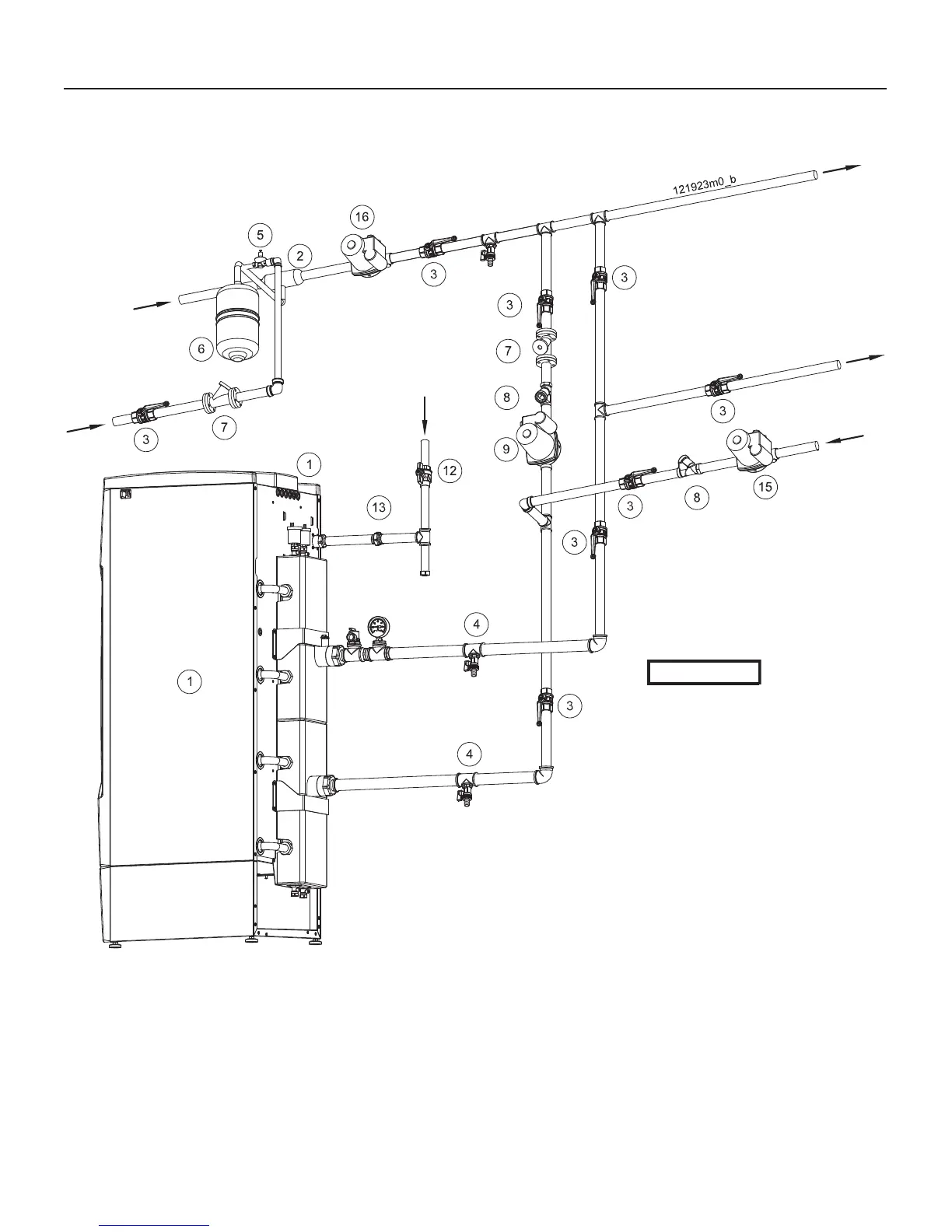
7 - INSTALLATION - IB boiler water connections
Figure 7-5 Piping of IB boilers model 399, 500, 750 and 1000
Heating
system
return
Supply to a
DHW indirect
water heater
(if needed)
Return from a
DHW indirect
water heater (if
needed)
Gas inlet
Heating
system
supply
Cold
water
make-up
1 = IB Boiler
2 = Air separator
3 = Ball valve
4 = Drain valve
5 = Filling valve
6 = Expansion tank
7 = Filter
8 = Back fl ow preventer
9 = Local boiler pump
12 = Manual Gas shut-off valve (Install manual shut-off
valve 5 ft (1.5m) above fl oor)
13 = Ground joint union
15 = Indirect water heater pump (DHW pump) (if needed)
16 = Heating pump (CH pump)
CAUTION!!!
This is a
concept drawing only. It is
up to the system designer
to determine the necessary
components, including
additional equipment and
any safety devices which
in the judgement of the
designer are appropriate,
in order to properly size,
confi gure and design
that system and to
ensure compliance with
building and safety code
requirements.

 Loading...