16
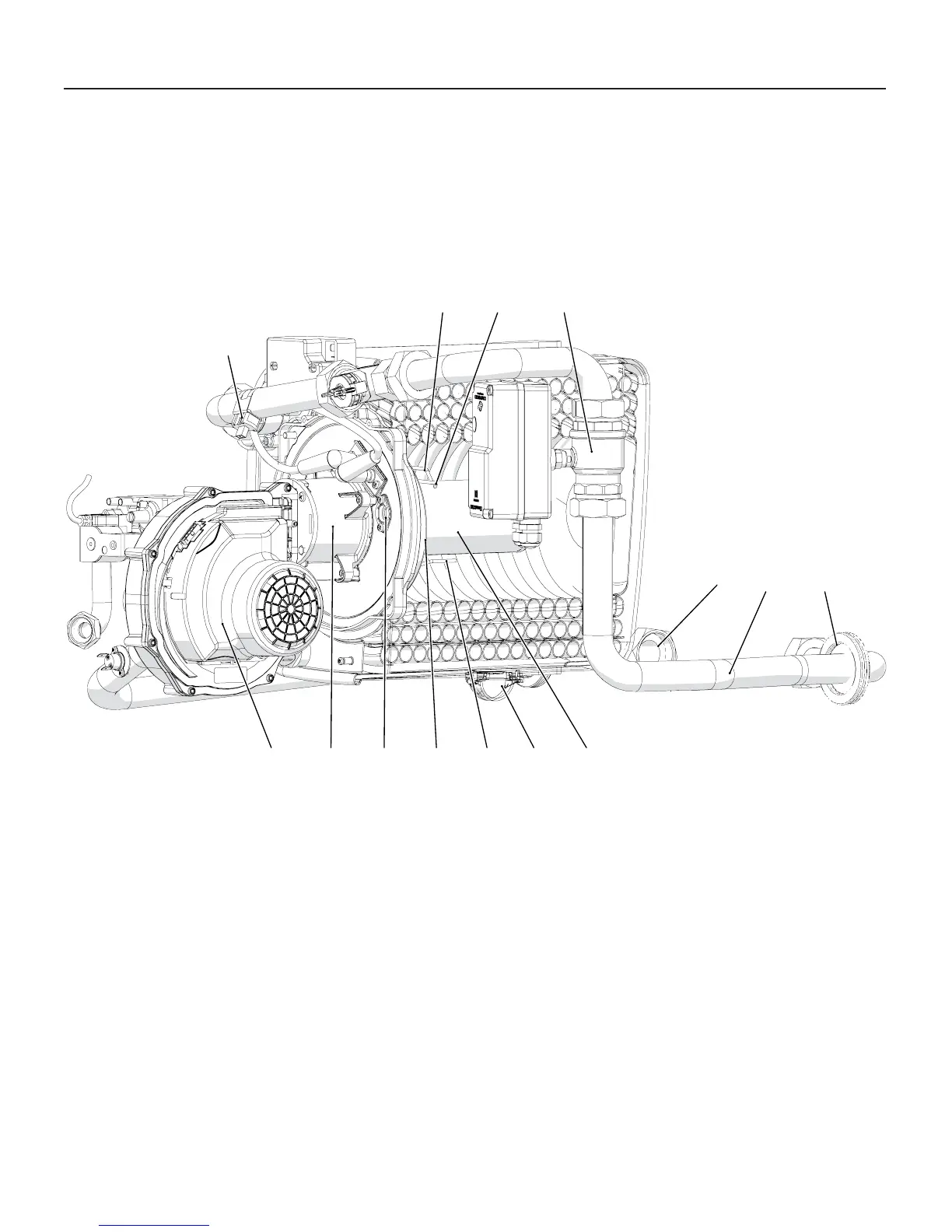
Figure 3-2 Burner unit main components
3 - MAIN COMPONENTS
19 - Burner surface
20 - Burner unit condesate discharge
21 - Detection electrode
22 - Thermal insulation
23 - Sight glass
24 - Raccord fan-burner (inside this fi tting ther’is a fl apper valve and
a magnetic control switch)
25 - Modulating Fan
7
2021 19
27 28
30
2223
26
24
18
25
29
020009.01.005
26 - Return temperature sensor (par. 1007)
27 - Left ignition electrode
28 - Right ignition electrode
29 - Motorized valve body (optional)
30 - Gasket

 Loading...