48
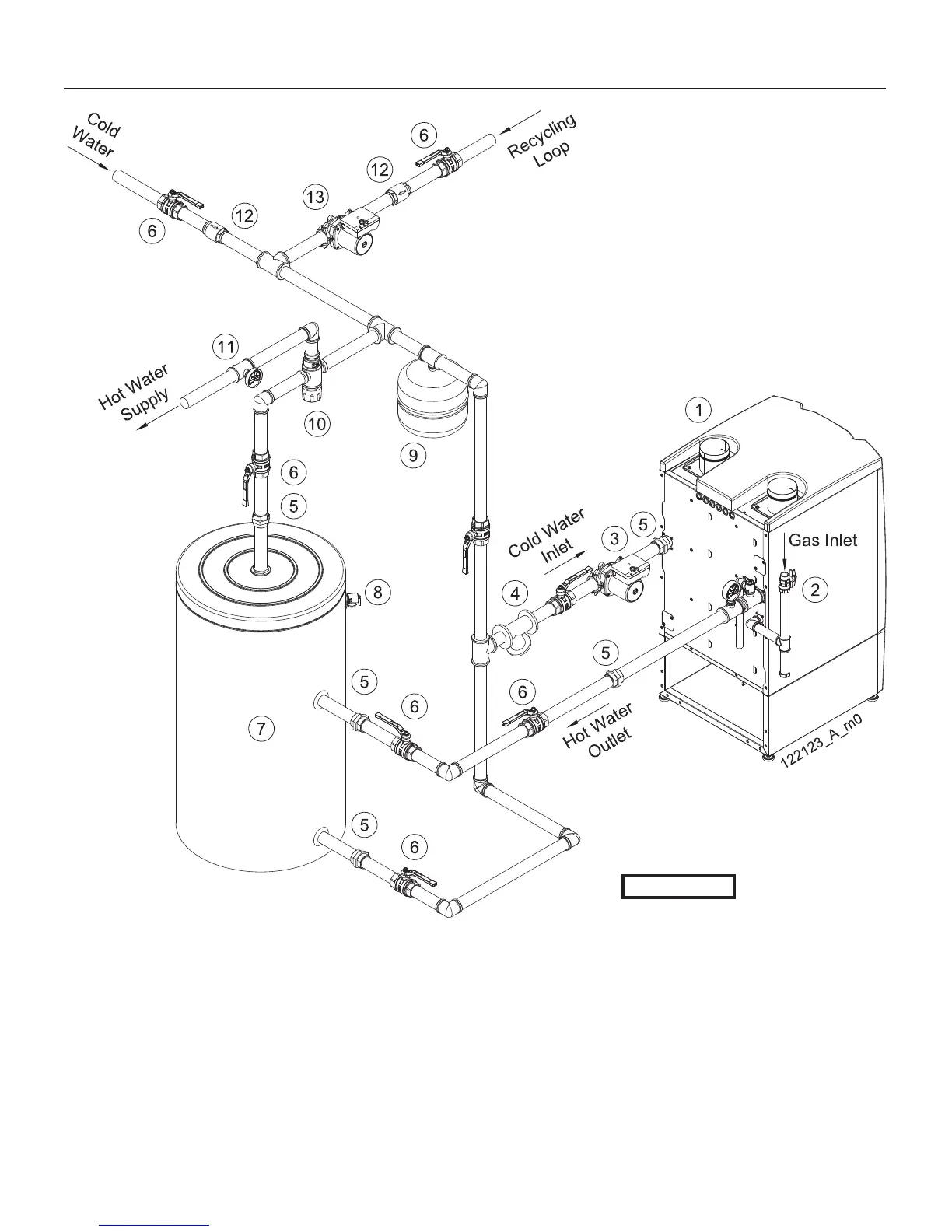
Figure 8-5 Piping of a IW water heater model 199
1 = Water heater
2 = Manual gas shut-off valve (Install manual
gas shut-off valve 5 ft (1.5m) above fl oor)
3 = Storage tank Pump (Local pump)
4 = Filter
5 = Union
6 = Ball valve
7 = Storage tank
8 = Storage tank T-P relief valve
9 = Expansion tank
10 = Mixing valve
11 = Temperature gauge
12 = Back fl ow preventer
13 = Recycling pump (If needed)
CAUTION!!!
This is a concept
drawing only. It is up to the
system designer to determine
the necessary components,
including additional equipment
and any safety devices
which in the judgement of
the designer are appropriate,
in order to properly size,
confi gure and design that
system and to ensure
compliance with building and
safety code requirements.
8 - INSTALLATION - IW water connections

 Loading...