89
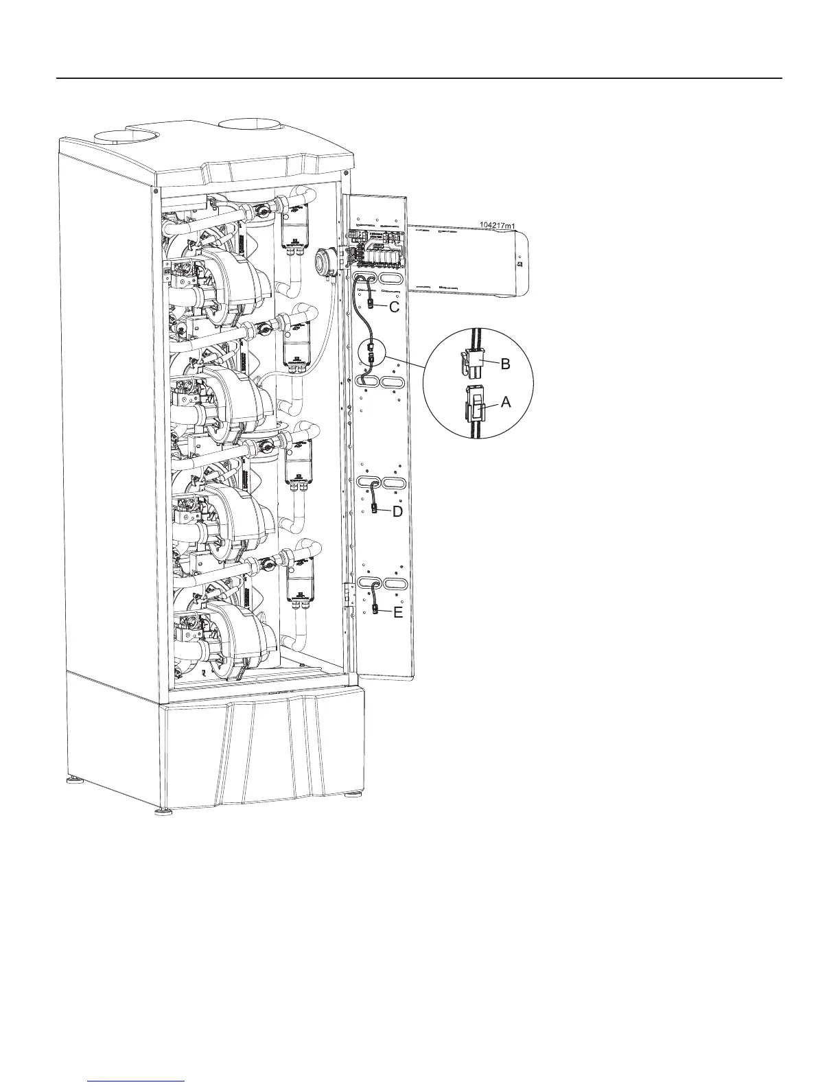
Figure 12-10 Moving display connection
After converting all burners:
15. connect plug “B” to plug “A” (See
Figure 12-10)
16. check the inlet gas pressure of the
unit, following Section 13.7;
17. check the capacity input of the unit
following Section 13.9;
18 - Attach to the front of the heater
the appropriate conversion label,
found in the conversion kit stating
the new type of gas adjustment of
the heater as follow:
a - Apply the label in Figure 12-8 if
the heater has been converted to
LP GAS;
b - Apply the label in Figure 12-9 if
the heater has been converted to
NATURAL GAS.
12 - INSTALLATION - Gas supply
A = Connector coming from Burner 1 (Master)
B = Connector coming from display
C = Connector coming from Burner 2
D = Connector coming from Burner 3 (Present only on models 750 and 1000)
E = Connector coming from Burner 4 (Present only on model 1000)
Burner 2
Burner 1
(Master)
Burner 3
Burner 4

 Loading...