3 - Logging Options
Logging Options (Apollo only)
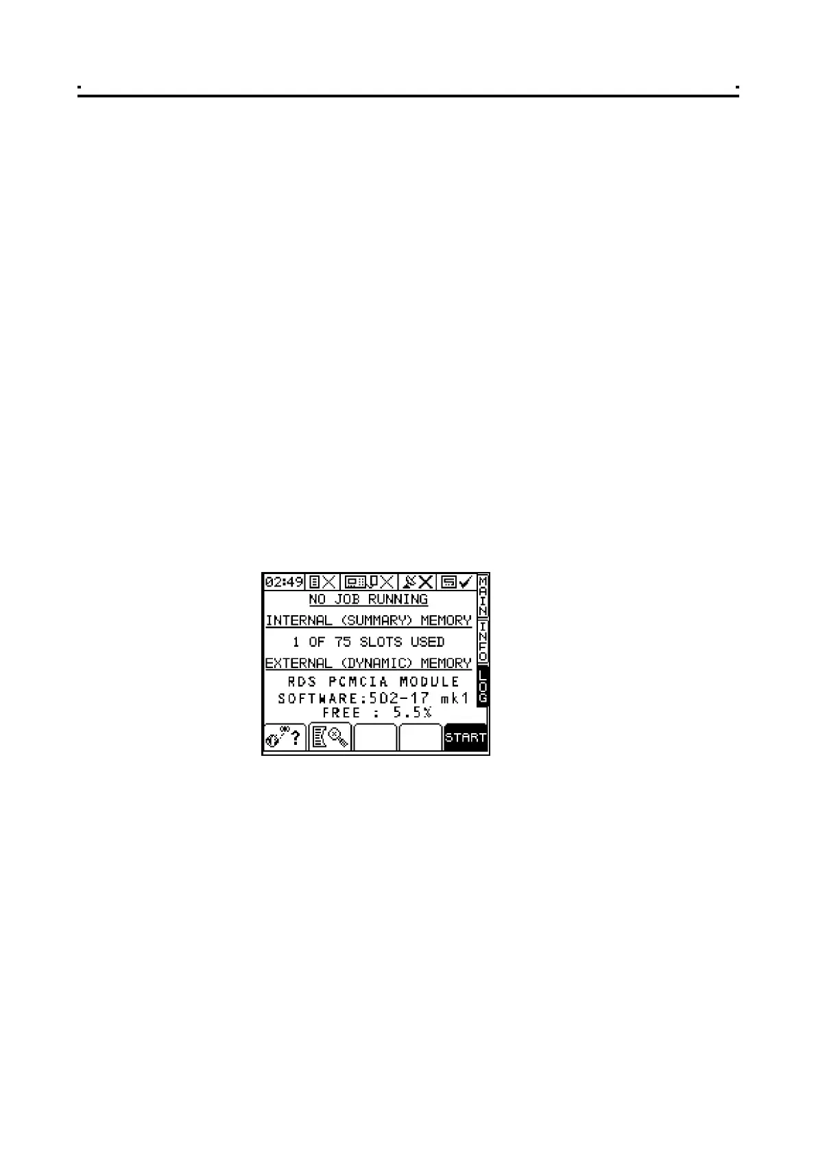
The Pro-Series has a separate LOG screen. Data is logged to internal (summary)
memory and/or external (dynamic) memory (fig. 16) depending on the logging option.
You can choose from three logging options. They are;
(i) APPLY FROM PLAN (Variable-Rate Treatment)
A variable-rate (or fixed-rate) treatment plan is imported from the RDS Data Card
Module, allowing the operator to commence a full VRT application. A full spray
application record of the actual application is generated and saved on the Data
Module. The associated work record file can be viewed in PLOT/PLAN. Job
summary data (iii) is also appended to the work record file.
(ii) LOG TREATMENT (Dynamic Data Logging)
A full spray application record is generated, logging rate and other parameters (e.g.
"tags") in real time, attributing this data to a specific location. The associated
"Dynamic Logging" file is viewed in PLOT/PLAN. A large amount of data is generated
by dynamic logging and therefore must be saved onto an RDS Data Card Module.
Job summary data (iii) is also appended to the dynamic logging file.
(iii) LOG SUMMARY ONLY (Field Data Logging)
For farm record keeping and traceability purposes, you can record a summary of
each job or work session in the internal memory, and subsequently download
directly to a PC, or print to an RDS ICP200 In-Cab Printer. The amount of summary
data for each job is small, and it is saved in the internal memory. The instrument can
store up to 75 individual job summaries. Options (i) and (ii) also require a GPS
receiver to be connected.
3.1 Hardware Setup
Connect the PCMCIA Card Module to the top serial port on the rear of the instrument,
and connect the DGPS receiver to the bottom port. The PS8000 must be configured
to recognise the Data Module and GPSInput (sections 4.5.1 and 4.6.1 respectively of
the calibration manual). For information on connecting and configuring RDS PF
hardware e.g. the Data Card Module, Secondary Software Module, DGPS Receiver,
cables etc, and data transfer to your PC, please refer to the "Precision Farming
Supplement".
NOTE: Mark I Data Modules: If you have a Mark I Data Module, always power it off before
inserting or removing a PCMCIA card, otherwise you risk corrupting data stored on the
card.
Mark II Data Modules: Mark II modules are only powered up when a PCMCIA card
is inserted. If there is no card in the module when it is connected to the instrument,
the module will not be detected. The PCMCIA card can be inserted or removed
without any risk of corrupting stored data. he module type, software, and free space is
identified on the LOG screen when the module is detected.
3
Figure 16
The LOG page