Reach PoE5 Tester Manual 1.8 03/25/2021 Page 5
2. General
2.1. Overview
Manufacturers of Ethernet Power Sourcing Equipment (PSE) such as Ethernet Switches
need to test PoE power functionality during manufacturing. Once a unit is in
manufacturing, it can be assumed that it has already been tested for full compliance with
the applicable IEEE 802.3 PoE standard. It is not cost-effective, nor necessary, to
perform full compliance testing at the manufacturing stage. What is needed is a
functional test that verifies the software’s ability to detect and control power, and the
basic connectors’ and magnetics’ ability to provide power and pass data.
The Reach RT-PoE tester family is designed for cost-effective, functional production
testing. It assumes that the PSE can be operated in a “diagnostic” mode whereby the
power control and detection functions of the PSE can be individually tested. Data
protocol features such as the Link Layer Discovery Protocol (LLDP) are not supported so
as to keep the cost of the tester low. Most switches provide a way of bypassing LLDP to
provide full power to a particular port. LLDP is implemented in firmware: if the unit can
pass data under power it can pass LLDP packets, and so testing LLDP functionality is not
necessary for a production test.
The Reach Power-over-Ethernet Tester Model RT-PoE5 provides diagnostic functional
testing of 24 PSE ports compatible with IEEE Standards 802.3af, 802.3at, and 802.3bt,
plus it will support data path speeds up to 10GBASE-T. It can draw up to 1000mA per
power pair (100W total over four pairs) while passing 10Gb traffic. It provides high
density with 24 Powered Device (PD) loads in a 1U high chassis.
Each RT-PoE5 section has a “UUT” port (Unit Under Test). The UUT port is connected
to the PSE and acts as a PD load to that port. The UUT data path is connected via power-
isolating magnetics to the adjacent UUT port (1 to 2, 3 to 4, 5 to 6, etc.). In this way, an
external data bit error tester or PSE test functionality can be used to test data integrity
while power load is enabled.
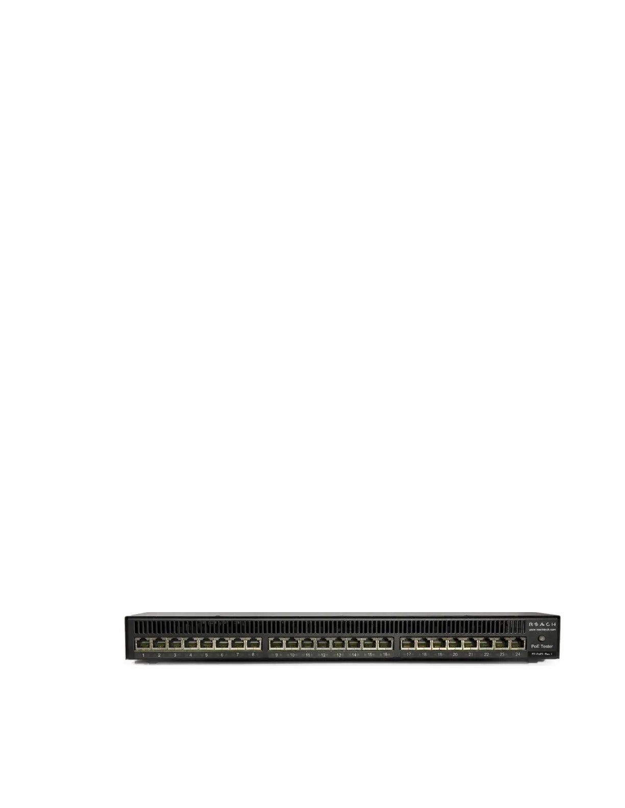
2.2. Front panel
Picture 1: Front of RT-PoE5
The front of the RT-PoE5.