RTL8169
2002/03/27 Rev.1.21
91
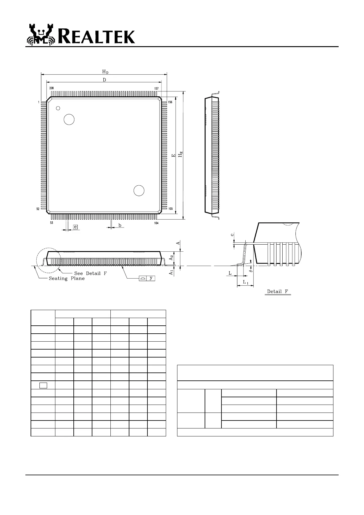
12. Mechanical Dimensions
Note:
Symbol Dimension in inch Dimension in mm 1.Dimensions D & E do not include interlead flash.
Min Typical Max Min Typical Max 2.Dimension b does not include dambar protrusion/intrusion.
A
0.136 0.144 0.152 3.45
3.65
3.85
3.Controlling dimension: Millimeter
A
1
0.004 0.010 0.036 0.10
0.25
0.91
4.General appearance spec. should be based on final visual
A
2
0.119 0.128 0.136 3.02
3.24
3.46
Inspection spec.
B
0.004 0.008 0.012 0.10
0.20
0.30
C
0.002 0.006 0.010 0.04
0.15
0.26
D
1.093 1.102 1.112 27.75
28.00
28.25
TITLE : 208L QFP ( 28x28 mm**2 ) FOOTPRINT 2.6mm
E
1.093 1.102 1.112 27.75
28.00
28.25
PACKAGE OUTLINE DRAWING
e
0.012 0.020 0.031 0.30
0.50
0.80
LEADFRAME MATERIAL:
H
D
1.169 1.205 1.240 29.70
30.60
31.50
APPROVE DOC. NO. 530-ASS-P004
H
E
1.169 1.205 1.240 29.70
30.60
31.50
VERSION 1
L
0.010 0.020 0.030 0.25
0.50
0.75
PAGE 22 OF 22
L
1
0.041 0.051 0.061 1.05
1.30
1.55
CHECK DWG NO. Q208 - 1
Y
- - 0.004 - - 0.10
DATE APR. 11.1997
Θ
0
°
-
12
°
0
°
-
12
°
REALTEK SEMICONDUCTOR CO., LTD