14
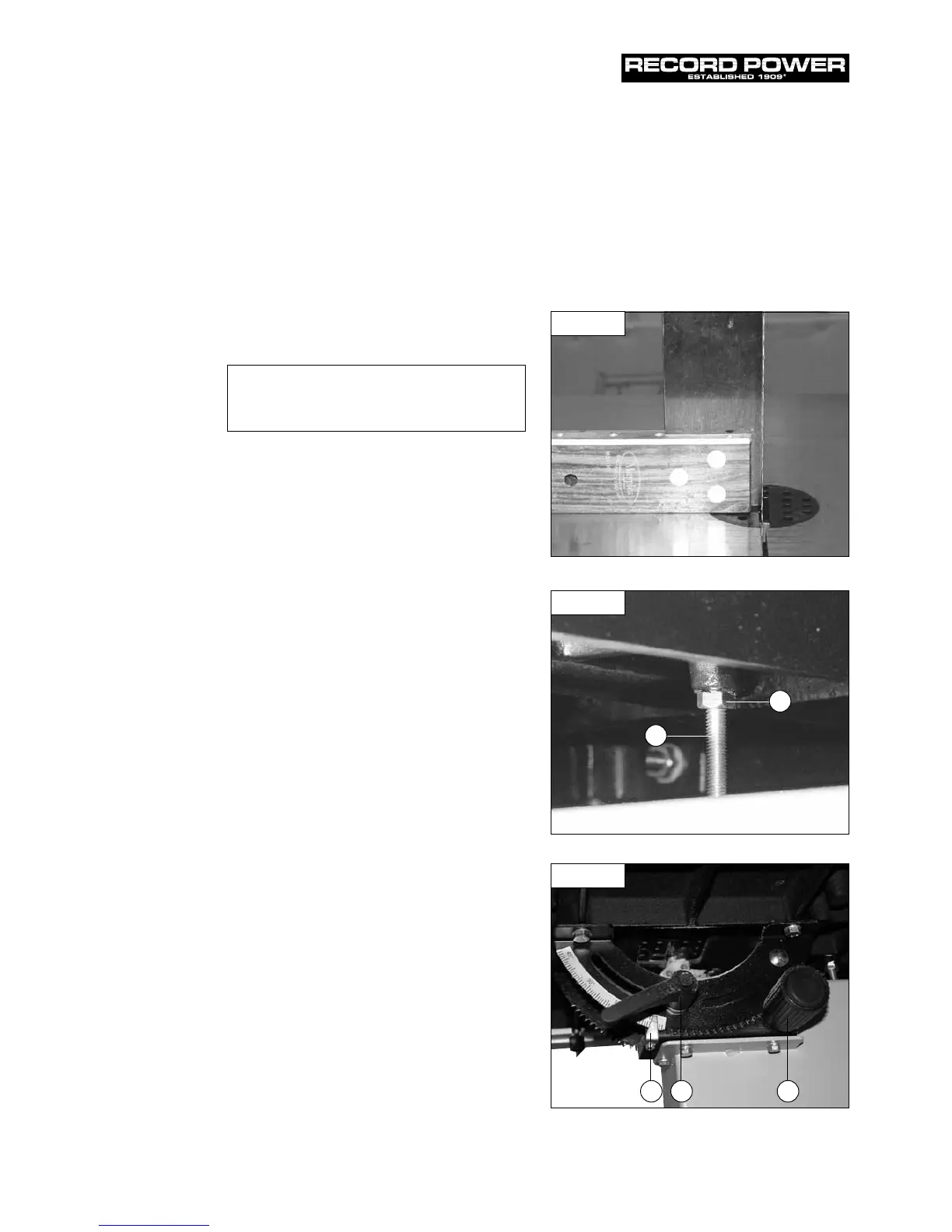
8. Setting Table Square to Sawblade
Tools Required:- Small 90º square (Not supplied)
The table can be set at 90º to the Bandsaw Blade
(Fig. 8.1) by adjusting the table stop screw (Fig. 8.2)
underneath the table.
1. First offer the square up to the blade to give an
indication of adjustment required. (Fig. 8.1)
2. If the table is not at 90º to the blade use table tilting
mechanism (Fig. 8.3) to adjust the table until it is 90º to
the blade. If the table stop screw (Fig. 8.2, A) position is
too high it may be necessary to wind this down out of
the way so 90º can be achieved.
3. Once the table is at 90º to the blade lock off the lock
handle on the table tilt mechanism to secure the table
position (Fig. 8.3).
4. Now set the table stop screw (Fig. 8.2, A), the table stop
screw should be adjusted to meet the flat registration
point (Fig. 8.2, B) on the underside of the table (now
set at 90º) to ensure that the table always returns to
square after tilting. The table stop screw is located
above the bandwheel on the lower bandwheel housing.
By first slackening the locking nut and then adjusting
the hex screw the table stop screw can be set correctly.
Re-tighten the locking nut making sure that the setting
is maintained.
Adjusting the Table Tilt Scale
Once the table is set at 90º to the Bandsaw Blade it may
be necessary to adjust the angle pointer on the angle
scale so any further angles are accurate. To do this use
a Phillips screwdriver to loosen the pan head screw and
adjust the pointer to 0º (Fig. 8.3, A).
Tilting the Table
The tilt mechanism will be used when squaring the table
to the blade. Tilt the table as follows: Loosen the lock
handle (Fig. 8.3, B) on the table trunnion. Turn the table
tilting knob (Fig. 8.3, C) to adjust the table angle. Use the
angle indicator scale on the trunnion bracket to find the
desired angle. Re-tighten the lock handle to secure
the table.
CAUTION! Before carrying out any adjustments or
maintenance ensure that the machine is isolated and
disconnected from the electricity supply.
Fig. 8.1
Fig. 8.2
A
B
Fig. 8.3
Setting the Table Stop at 90º to
the Sawblade
A BC