Overview | 9
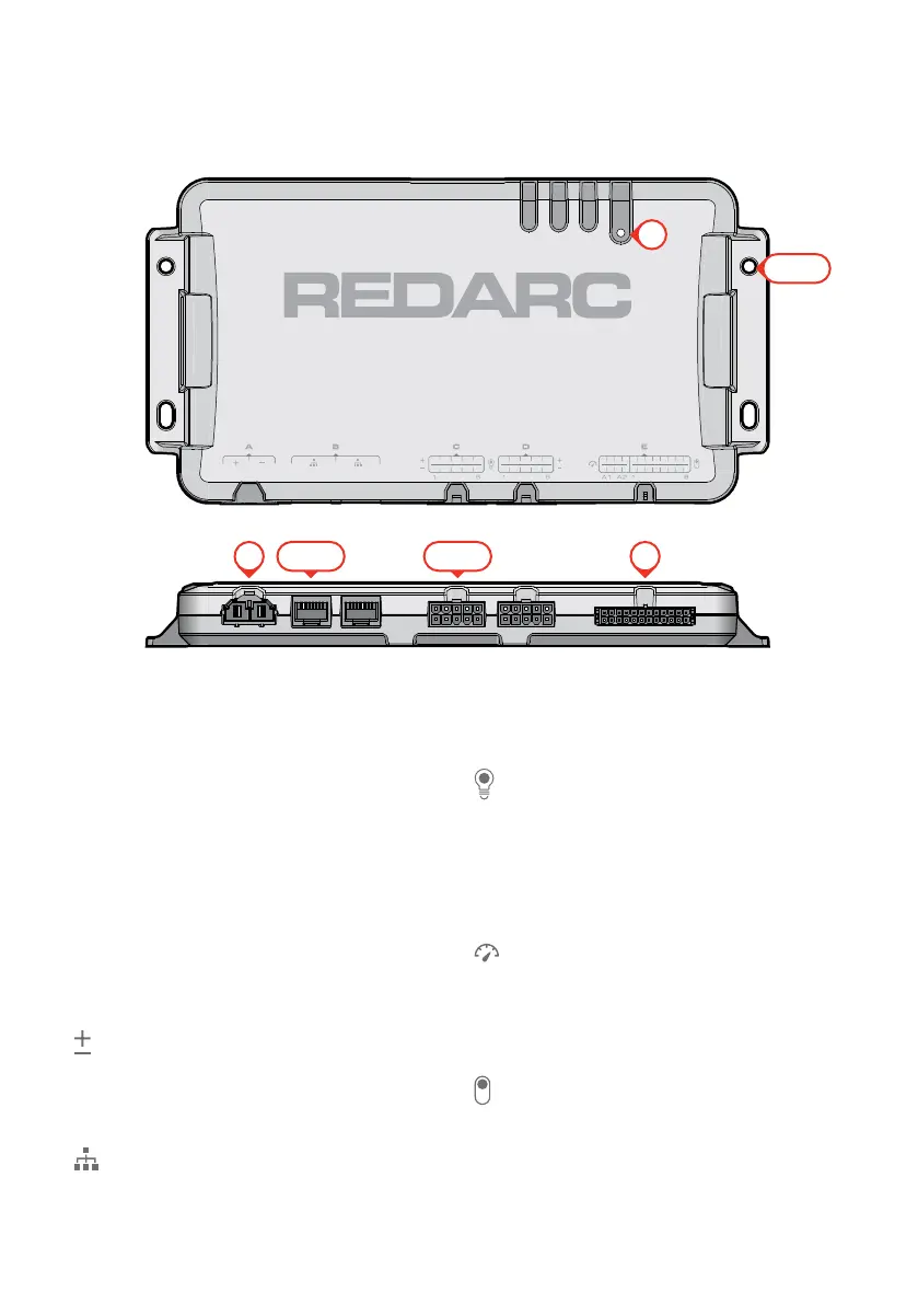
1. Status LED
Red LED that illuminates for 5 seconds
upon start-up, and also indicates Faults
(page41).
2. Mounting Holes (×4)
Fastening points for mounting the Main Unit
(page13).
3. Power Input Interface
A: Accepts power from a 12 V
auxiliarybattery (page27).
4. R-Bus Network Interface (×2)
B: Connect RedVision
®
R-Bus compatible
devices such as The Manager and the
RedVision
®
Display (DISP4300).
5. Outputs Interface (×2)
C / D: 10 A software-fused outputs for
powering loads such as a fridge, fans,
pumps, and lights with capability for
dimming LED lights.
6. Inputs Interface
E A1/A2: Sensor inputs (analogue) for
connecting compatible tank level sensors
(e.g. water level or fuel level), and devices
that can measure voltage (e.g. measuring
secondary battery voltage).
E 1–8: Switch inputs (digital) for connecting
switches that can be configured to remotely
turn On/Off devices in the RedVision
®
system, or can control dimming functionality.
3
6
1
2 (×4)
4 (×2) 5 (×2)
PARTS OF THE MAIN UNIT