Ref.: RX182/006
Version 01/2017 - English
This document must not be reproduced nor information therein disclosed without our authorization
Page 8 / 28
4 MOTOR INSTALLATION
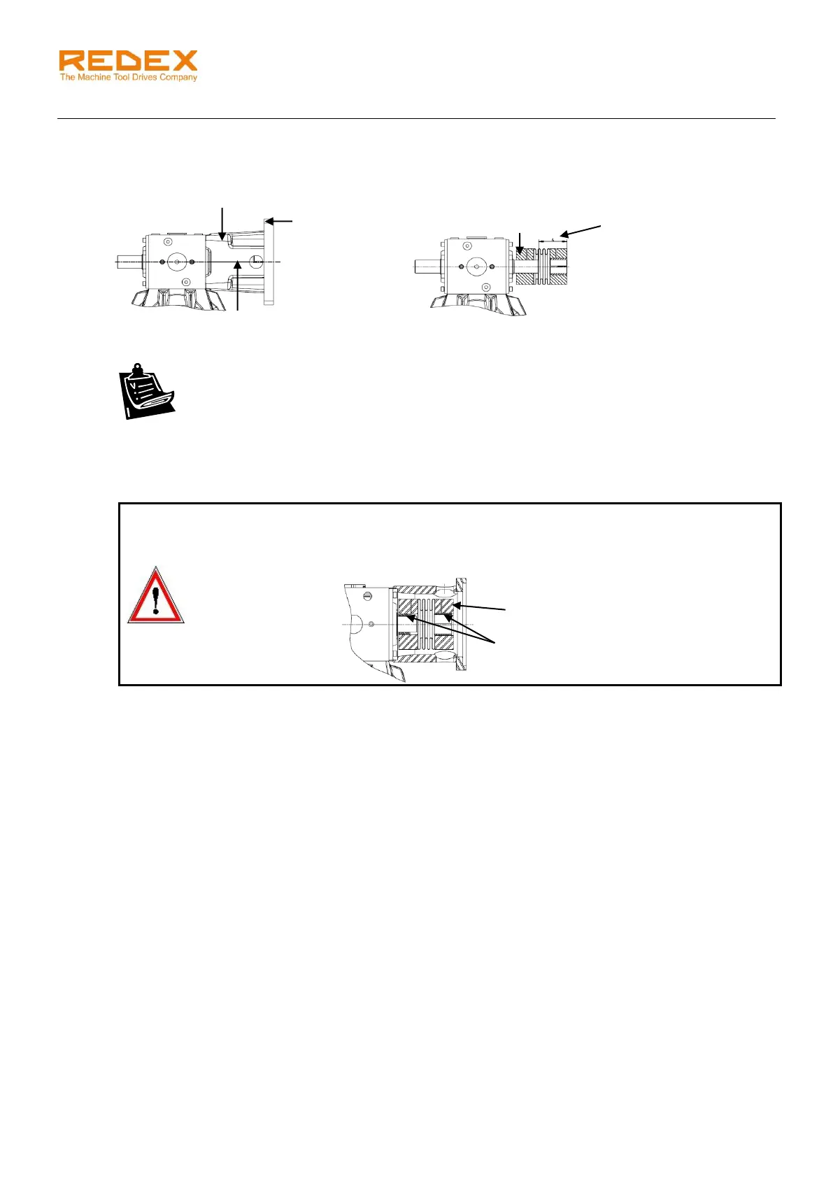
4.1 MF-type motor flange mounting (for right angle configurations SRP.R and cylindrical shafts)
Respect the following instructions to install the motor flange.
1. Clean the mounting surfaces to be fitted together i.e.: coupling, pilot diameter of the motor, the flange
and the motor shaft.
2. Mount the coupling (with or without shaft adapter) onto the bevel box shaft.
WARNING!
When the coupling bore is bigger than the diameters of the motor shaft or bevel box shaft, a
shaft adapter is supplied with the coupling. The groove of this adapter must be aligned with
the coupling split bore.
3. Place the coupling with respect of the distance A (see picture & table).
4. Tighten the screw of the coupling on the bevel box side (adequate tightening torque: see table 1).
5. Mount the MF flange and tighten its 4 fixing screws (“screws MF Bevel box & torque” in table 1).
6. Carefully slide the motor shaft into the coupling bore (with the shaft adapter if supplied) until the motor
face sits in the pilot diameter bore of the MF flange.
7. Tighten the motor screws one after the other in several passes (see tightening torque in table 2).
8. Tighten the other screw of the coupling (at the adequate tightening torque: see table 1).
the motor