EasyManua.ls Logo

REDEX SRP0 - Srp Mounting Height Setting

Default Icon
176 pages
Print Icon
To Next Page IconTo Next Page
To Previous Page IconTo Previous Page
Loading...
Ref.: RX182/006
Version 01/2017 - English
This document must not be reproduced nor information therein disclosed without our authorization
Page 19 / 28
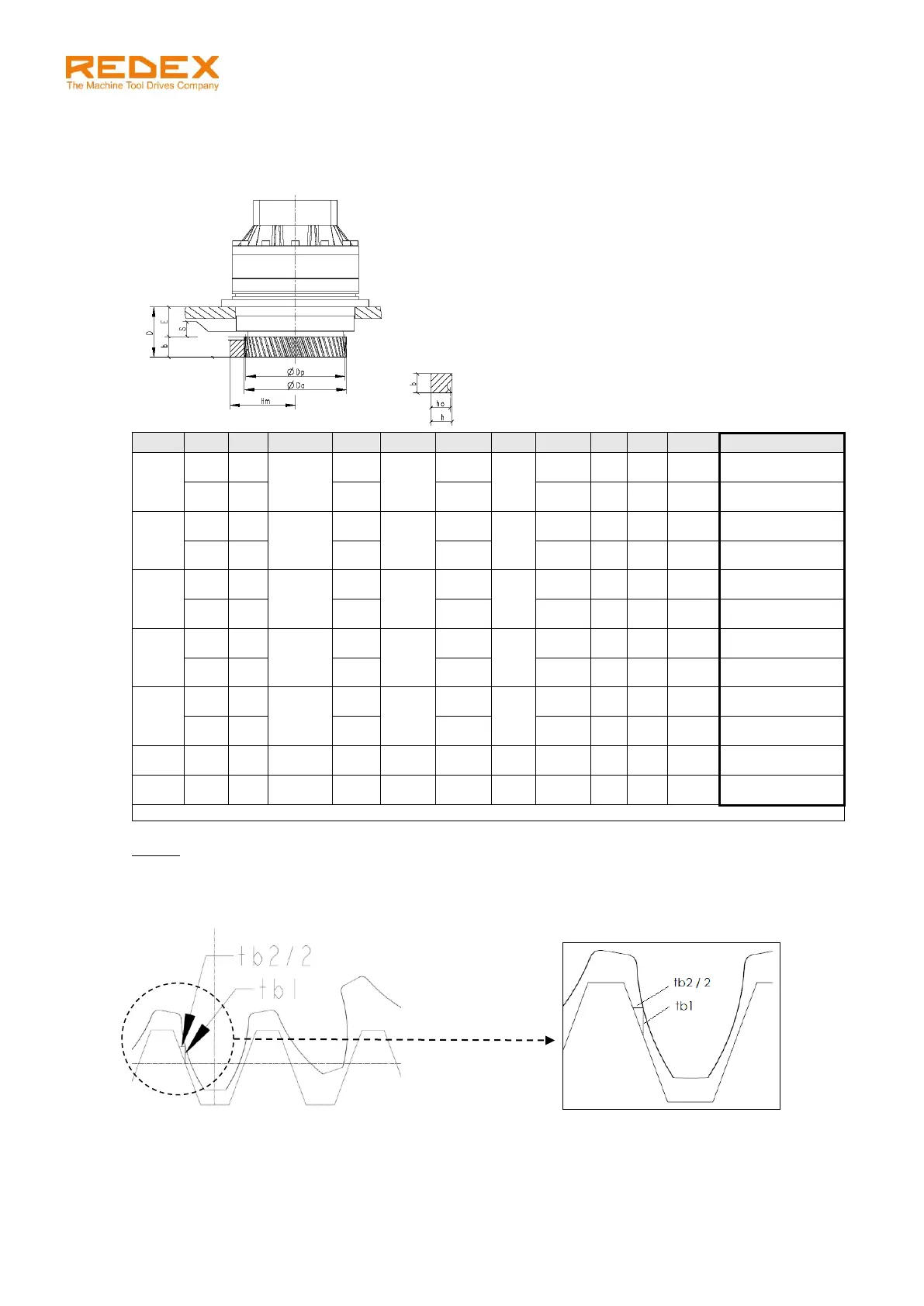
7.3 SRP mounting height setting
Determine and respect the mounting height of the SRP axis.
Respect the value hm that includes the tooth radial clearance tb
1
.
Size
Mo
Z
Dp
Da
E
D
S
tb
1
b
h
ho*
hm
0
2
45
95.49
100
29
59
6
0.075
30
24
22
70.075
+0.02
-0.02
2.5
36
101
29
0.1
30
24
21.5
69.6
+0.025
-0.025
1
2.5
42
111.41
117
38
68
6
0.1
30
24
21.5
77.6
+0.025
-0.025
3
35
118
73
0.1
35
29
26
82.1
+0.025
-0.025
2
3
52
165.52
173
50
85
8.5
0.1
35
29
26
109.6
+0.025
-0.025
4
39
175
95
0.15
45
39
35
118.65
+0.025
-0.025
3
4
45
190.99
201
66
111
12
0.15
45
39
35
131.65
+0.025
-0.025
5
36
203
121
0.2
55
39
34
130.7
+0.05
-0.05
4
5
42
222.82
236
75
130
15
0.2
55
39
34
147.2
+0.05
-0.05
6
35
238
141
0.2
66
49
43
156.2
+0.075
-0.075
5
8
15
127.32
147
99
178
9
0.3
79
79
71
137.8
+0.1
-0.1
6
10
14
148.54
177
126.5
225.5
11
0.4
99
99
89
168.9
+0.1
-0.1
* According to standard rack manufacturers (Güdel, Atlanta, etc…)
NOTE:
The machine frame supporting the unit must allow the adjustment of the distance centre hm.
The tooth radial clearance t
b1
(as well as the backlash between rack and pinion t
b2
, mentioned in the next
chapter) is detailed in the sketch below:

Table of Contents