TESTING the system
After validating and uploading the project to the M1 and connecting all the safety
devices, you must test the system to verify its correct operation.
This is done by forcing a change of status for each safety device connected to the
MOSAIC to check that the status of the outputs actually changes.
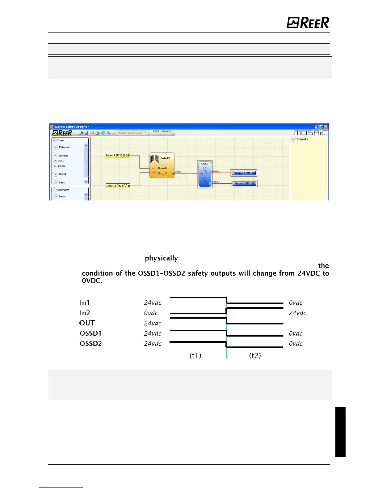
The following example is helpful for understanding the TEST procedure.
Figure 52
(t1) In the normal operating condition (E-GATE closed) Input1 is closed, Input2 is
open and the output of the E-GATE block is set to high logic level; in this mode
the safety outputs (OSSD1/2) are active and the power supply to the relative
terminals is 24VDC.
(t2) When the E-GATE is opened, the condition of the inputs and thus of
the outputs of the E-GATE block will change: (OUT= 0VDC--->24VDC);
If this change is detected the mobile E-GATE is connected correctly.
For the correct installation of each external sensor/component refer to their
installation manual.
This test must be performed for each safety component in the project.
 Loading...


